Method of Solids Control and Fluid Recovery in Drilling Operations

a drilling operation and solids control technology, applied in the direction of filtration separation, separation process, borehole/well accessories, etc., can solve the problems of high drilling difficulty, high cost, and need for new replacement mud, and achieve the effect of reducing the number of drilling problems

Inactive Publication Date: 2016-03-17
HURST JASON
View PDF0 Cites 13 Cited by
  • Summary
  • Abstract
  • Description
  • Claims
  • Application Information

AI Technical Summary

Problems solved by technology

Additionally, the cuttings and other solids must be disposed of, often offsite, resulting in significant expense and effort.
Depending on the final condition of the cuttings, there may also be environmental concerns with their disposal.
This results in significant contamination of the solids with chemical based muds to levels requiring environmental regulation as to their disposal, and requires new replacement mud, at significant cost, to be utilized to replace lost volume.
Mud may represent over fifteen percent (15%) of drilling costs, but may cause a much higher percentage of drilling problems.
Increasing environmental concerns have limited the use of some of the most effective drilling fluids and additives due to the cost of disposal concerns of fluid laden solids.
With drilling fluid being such a large percentage of drilling cost, all effort is made to recapture and recycle drilling fluid.
But with such a critical weighing of factors in fluid density, viscosity, rheology, and other characteristics; the drilling fluids must be properly treated and cleaned before reuse, or any value in such recycling will be lost due to equipment wear and tear, and the efforts necessary to reweight fluids to proper consistency.
This discarded mud has costs associated with its replacement in the system to keep the total mud volume where it needs to be fo

Method used


Image

  • Method of Solids Control and Fluid Recovery in Drilling Operations
  • Method of Solids Control and Fluid Recovery in Drilling Operations
  • Method of Solids Control and Fluid Recovery in Drilling Operations

Examples


Embodiment Construction

[0032]Described herein is a method of solids control on a drilling rig which results in increased efficiency of solids disposal, cleaner mud recycling, and methods that keep breakdowns in solids control equipment from affecting rig operations.

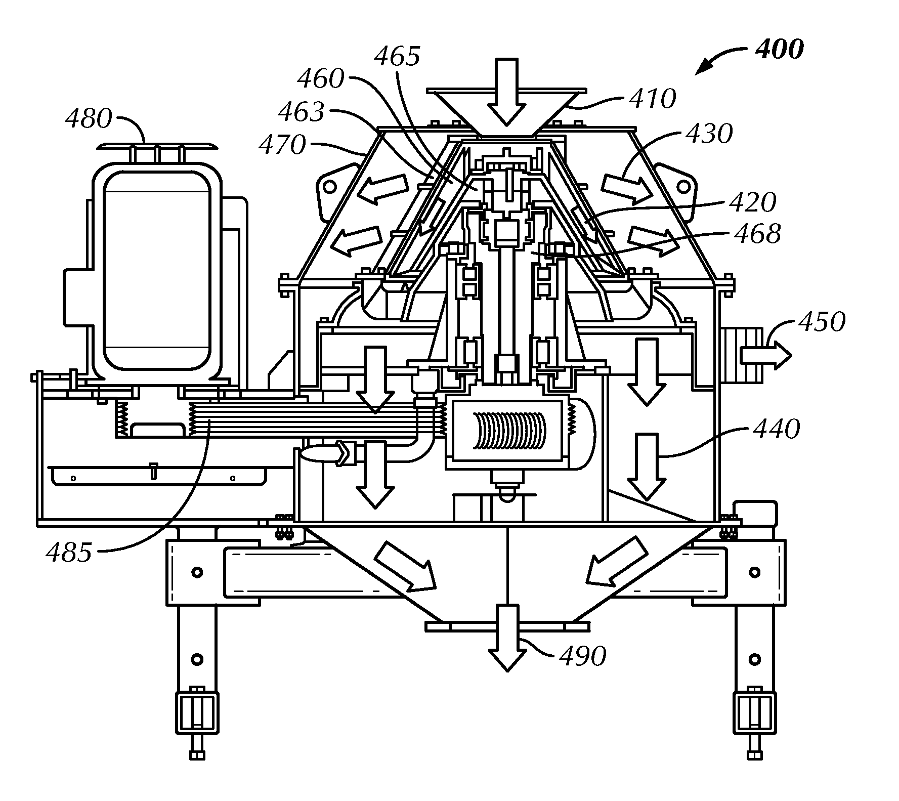
[0033]Typical rig operations have a plurality of shakers which out feed at approximately ten and a half feet or more above grade. The inventor utilizes a large collection hopper with an integrated auger in the bottom of the hopper which connects to a hard-piped transport auger feeding a vertical dryer. The bottom of the hopper is sloped at least thirty degrees toward the middle where the auger is positioned to effectively empty cuttings from the entire hopper. The hopper in the preferred embodiment has sides no more than six and a half feet above grade, a length in excess of twenty-four feet, and a width of approximately six feet.

[0034]An adjustable cover spans at least the length of the hopper and exceeds the width of the hopper on at least on...


PUM

PropertyMeasurementUnit
Angleaaaaaaaaaa
Lengthaaaaaaaaaa
Angleaaaaaaaaaa

Abstract

A method of processing mud laden cuttings from a rig's wellbore comprising collecting the cuttings from a plurality of shale shakers into a hopper, feeding the collected cuttings to an improved vertical dryer, continually recirculating the fluids from the dryer until ready for further processing, mixing the fluids with flocculates and diluting them before processing through high speed centrifuge and barite recovery centrifuges.

Description

CROSS-REFERENCE TO RELATED APPLICATIONS[0001]Not applicableSTATEMENT REGARDING FEDERALLY SPONSORED RESEARCH OR DEVELOPMENT[0002]Not applicable.NAMES OF PARTIES TO A JOINT RESEARCH AGREEMENT[0003]Not applicable.REFERENCE TO SEQUENCE LISTING, A TABLE, OR A COMPUTER PROGRAM LISTING APPENDIX SUBMITTED ON COMPACT DISC[0004]Not applicable.BACKGROUND OF THE INVENTION[0005]The invention relates to an apparatus and method for separating liquid from liquid laden solids discarded from a first recovery process and particularly, but not exclusively an apparatus and method for separating remaining liquid from liquid laden cuttings discarded from a drilling shale shaker recovery apparatus.[0006]In the drilling of a borehole in the construction of an oil or gas well, a drill bit is arranged on the end of a drill string, which is rotated to bore through a formation. The drilling mud is pumped through the drill string to the drill bit to lubricate the bit, and carry the cuttings produced by the bit a...

Claims


Application Information

Patent Timeline
IPC IPC(8): E21B21/06B01D21/01B01D21/26B01D33/03
CPCE21B21/066B01D33/03B01D21/262B01D21/01E21B21/01
Inventor HURST, JASON
Owner HURST JASON
Why Eureka
Try Eureka