Scan method for a touch panel and touch device

a touch panel and scanning method technology, applied in the field of scanning methods for touch panels, can solve the problems of still waste electricity and waste electricity, and achieve the effect of overcoming the shortcoming of a conventional scanning method, low electricity cost, and high sensing valu

Inactive Publication Date: 2016-03-17
ELAN MICROELECTRONICS CORPORATION
View PDF8 Cites 35 Cited by
  • Summary
  • Abstract
  • Description
  • Claims
  • Application Information

AI Technical Summary

Benefits of technology

[0011]An objective of the present invention is to provide a scan method with less electricity cost and high sensing values to effectively overcome the shortcoming of a conventional scan method with high electricity cost and low sensing values.
[0018]The scan method in accordance with the present invention defaults the baselines and the thresholds respectively corresponding to the cursory scan mode and the fine scan mode. In cursory scan mode, multiple traces are driven simultaneously and the signals from the traces are received simultaneously to save electricity than the fine scan mode that the traces are driven in sequence. The cursory scan mode is used to first determine whether a touch objects exists. When the touch object do exist, the fine scan mode is then operated to determine the coordinate of the touch object. Therefore, the present invention can reduce the electricity waste.
[0043]Based on the foregoing touch device, the sensing signals are received and existence of the touch object is determined by the outer detecting circuit in cursory sensing mode and the non-operating time of the receiving unit and the processor of the controller are extend to save electricity more efficiently. Moreover, the present invention provides a scan method for increasing sensing value to the touch panel including following steps:
[0049]In conclusion, using the cursory scan mode to determine the existence of the touch object, touch panel is scanned with less electricity cost in general condition. Driving multiple traces simultaneously and receiving the signals from the traces simultaneously enlarge the sensing value to detect the touch object with lower sensing signal. Therefore, the present invention reduces the electricity waste and enlarges the sensing value.

Problems solved by technology

Since the sleep mode of the conventional scan method is setting to save electricity, but actually it still waste electricity.
When the touch device is not touched for a long time, the conventional scan method still detect the coordinate of the touch object by waking up the touch device in regular period and entering the fine scan mode with high electricity cost, the conventional scan method waste electricity since no touch object exist.
Furthermore, the conventional scan method drives each trace in sequence by the driving unit and receives the sensing signal of each trace in sequence by the receiving unit, when user touch the touch panel with glove, the sensing signal is lower and the touch object existence can't be determined correctly and the coordinate of the touch object also can't be determined in further, it is inconvenient when using touch panel.

Method used


Image

  • Scan method for a touch panel and touch device
  • Scan method for a touch panel and touch device
  • Scan method for a touch panel and touch device

Examples


first embodiment

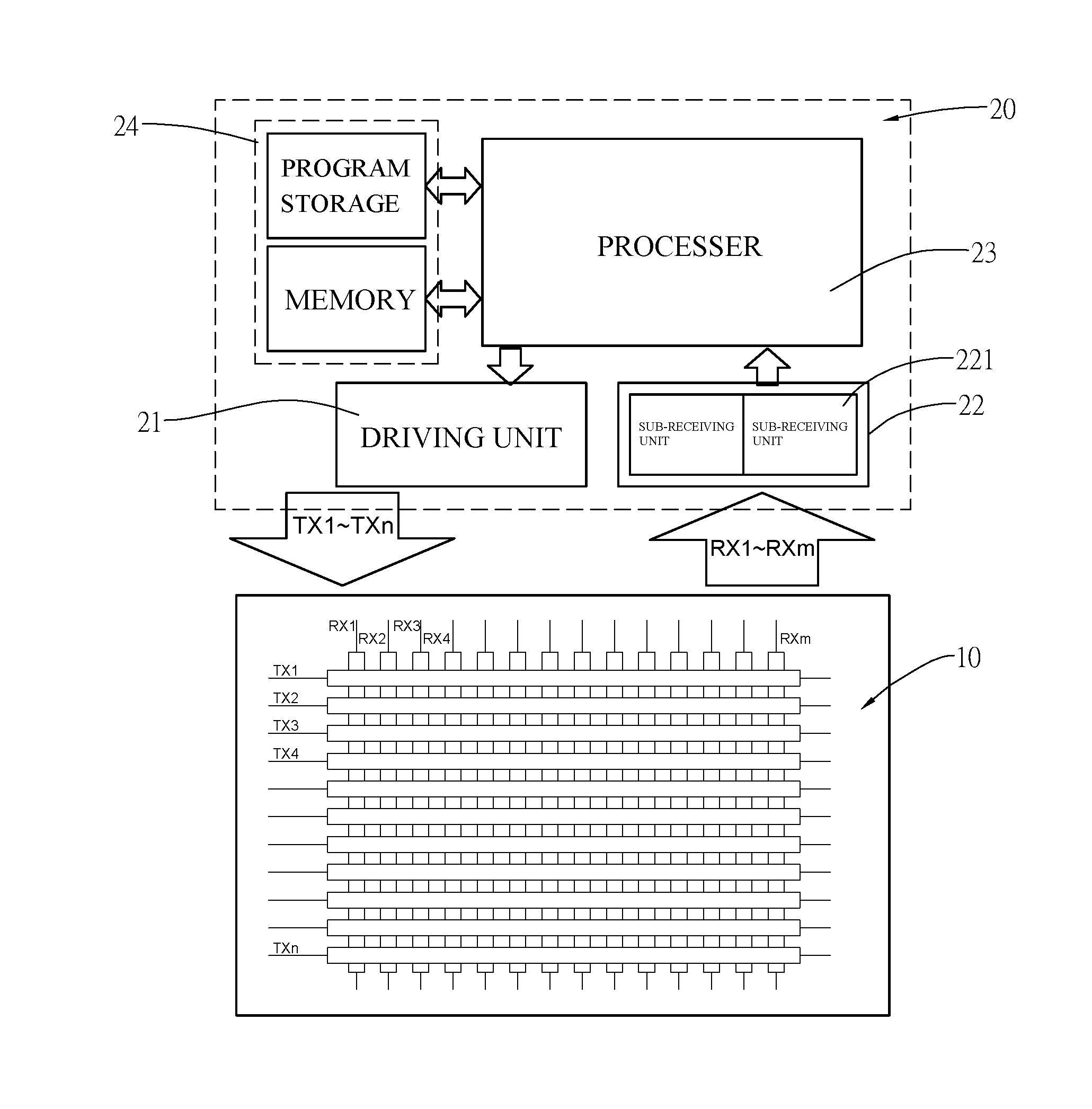
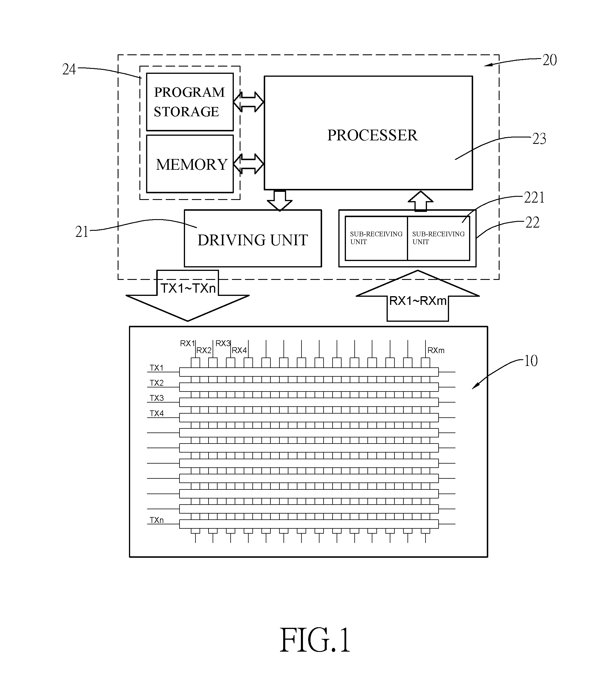
[0060]With reference to FIG. 1, the touch device in accordance with the present invention comprises a touch panel 10 and a controller 20.

[0061]The touch panel 10 has p traces including multiple first-axis traces and second-axis traces across each other. Taking self-capacitance scanning as an example, the p traces are both the driving lines and the receiving lines, taking mutual-capacitance scanning as shown in FIG. 1 as an example, the first-axis traces TX1˜TXn are the driving lines and the second-axis traces RX1˜RXm are the receiving lines.

[0062]The controller 20 connects to the touch panel 10 and includes a driving unit 21, a receiving unit 22, a processor 23 and a memory unit 24. The processor 23 controls the driving unit 21 to drive the driving lines of the touch panel 10. The receiving unit 22 receives the sensing signal from the receiving line of the touch panel 10 and then the processor 23 further deals with the sensing signal. In the first embodiment, the first-axis trace TX...

second embodiment

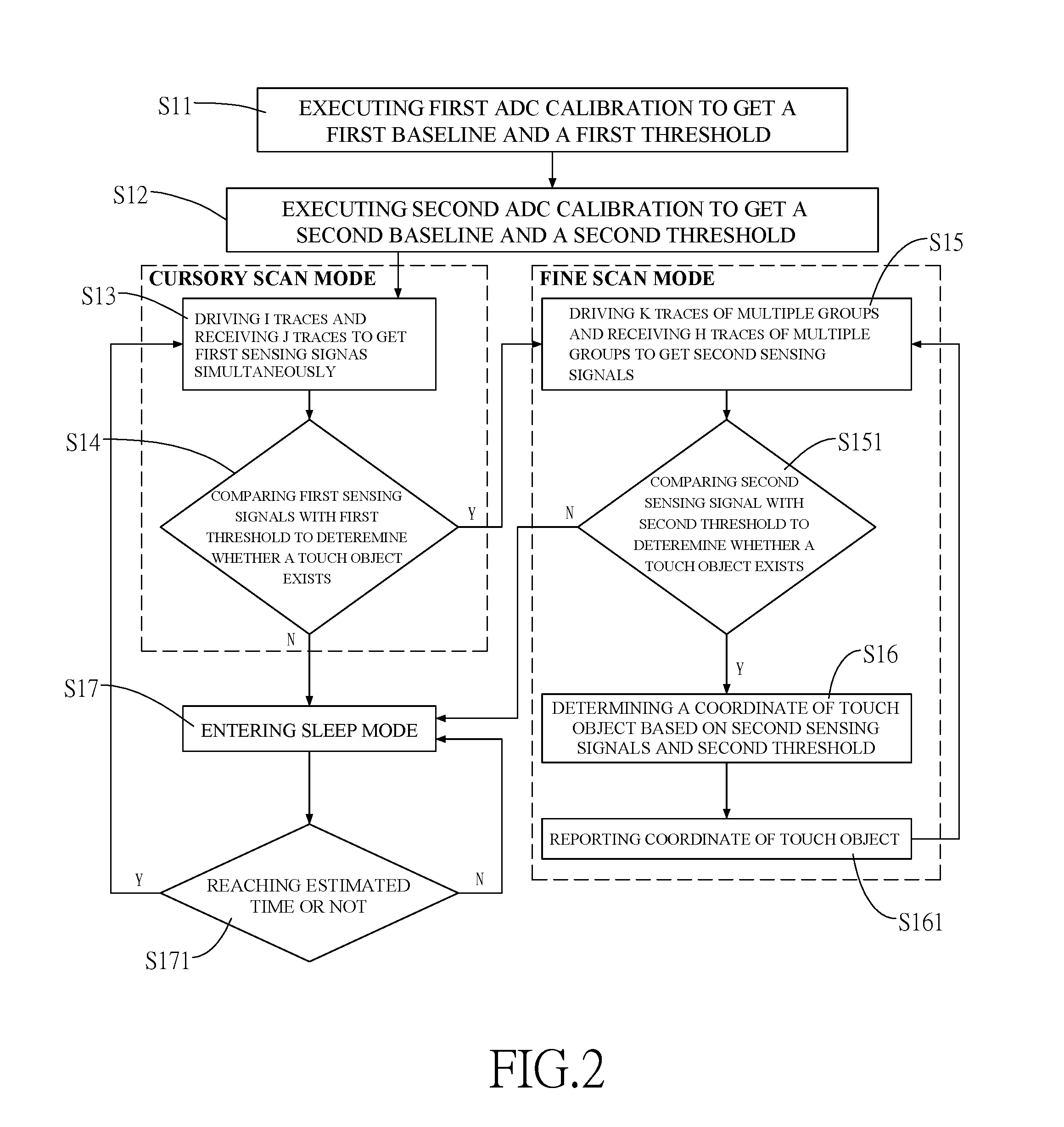
[0075]With the reference of FIG. 5, the steps of the scan method in accordance with the present invention S11˜S14 is the same with the steps S11˜S14 in the flow chart shown as FIG. 2 and adds steps for adjusting the baseline. The step S14 includes the following steps: Adjusting the first baseline and the first threshold: The first baseline and the first threshold are further compared when no touch object is determined by the processor 23 (S18). Based on the comparison result, the first baseline or the first threshold is adjusted and the adjusted first baseline or the adjusted first threshold is stored back to the memory unit 24; or the first baseline is adjusted first, and then the first threshold is adjusted based on the adjusted first baseline (S20). The adjusted first threshold is stored back to the memory unit 24. Then the sleep mode S17 is entered and the step S171 is executed. When the first sensing signal is bigger than the first baseline, a V1 value is added to the first bas...

third embodiment

[0087]With reference of FIG. 8, the scan method in accordance with the present invention has following steps:

[0088]Executing the first ADC calibration (S31): The first ADC calibration is executed to acquire the first baseline and the first threshold is set based on the first baseline;

[0089]Acquiring the first sensing signal (S32): The i traces are driven and the sensing signals of the j traces are received simultaneously;

[0090]Determining whether touch object exists (S33): The first sensing signals are compared with the first threshold to determine whether touch object exists;

[0091]Calculating the coordinate of the touch object (S34): if the touch object do exist, the coordinate of the touch object is determined and return to the steps of acquiring the first sensing signal (S32);

[0092]Determining if all the traces has scanned (S331): Whether all of the default traces has scanned or not are determined. If not all of the default traces are scanned, return back to the step (S32). If al...


PUM


Abstract

The present invention relates to a scan method for a touch panel and a touch device. It operates two different Analog-to-Digital Converter calibrations to have different baselines and thresholds corresponding respectively to a cursory scan mode and a fine scan mode. In cursory scan mode, multiple traces are driven simultaneously and the signals from the traces are received simultaneously to enlarge the sensing value so that a touch object with a lower sensing signal is also detected. Further, the cursory scan mode with less electricity cost is used to first determine whether touch objects exists. When the touch objects do exist, the fine scan mode with more electricity cost is then operated. Therefore, the present invention can further reduce the electricity waste.

Description

CROSS-REFERENCE TO RELATED APPLICATIONS[0001]This application is based upon and claims priority under 35 U.S.C. 119 from Taiwan Patent Application No. 103131482 filed on Sep. 12, 2014, which is hereby specifically incorporated herein by this reference thereto.BACKGROUND OF THE INVENTION[0002]1. Field of the Invention[0003]The present invention is related to a scan method for a touch panel, especially to a method to scan the touch object on the touch panel of electronic device.[0004]2. Description of the Prior Arts[0005]Touch panel is common used in high-tech product that is used as input device in the electronic device. There are multiple traces in the touch panel that the traces are driven by a driving unit controlled by a processor, and the sensing signals of the traces are received by a receiving unit, whether touch object exist or not is determined based on the sensing signal and the coordinate of the touch object is further determined.[0006]With reference of FIG. 9, to ensure t...

Claims


Application Information

Patent Timeline
Patent Type & Authority Applications(United States)
IPC IPC(8): G06F3/041
CPCG06F3/0418G06F1/3228G06F1/3231G06F1/3206G06F3/041661G06F3/0446G06F3/044
Inventor CHIANG, CHIA-CHANGTSENG, YAO-CHIN
Owner ELAN MICROELECTRONICS CORPORATION
Why Eureka
Try Eureka