Mobile telephone, apparatus, method and computer implementable instructions product
a technology of mobile telephones and products, applied in the field of communication systems, can solve the problems of different overall energy consumption of mobile telephones (both active and idle) served by base stations, and achieve the effect of minimising the failure of system message reception and optimizing power savings
- Summary
- Abstract
- Description
- Claims
- Application Information
AI Technical Summary
Benefits of technology
Problems solved by technology
Method used
Image
Examples
first embodiment
DRX Cycle Synchronisation Using Current Time Information
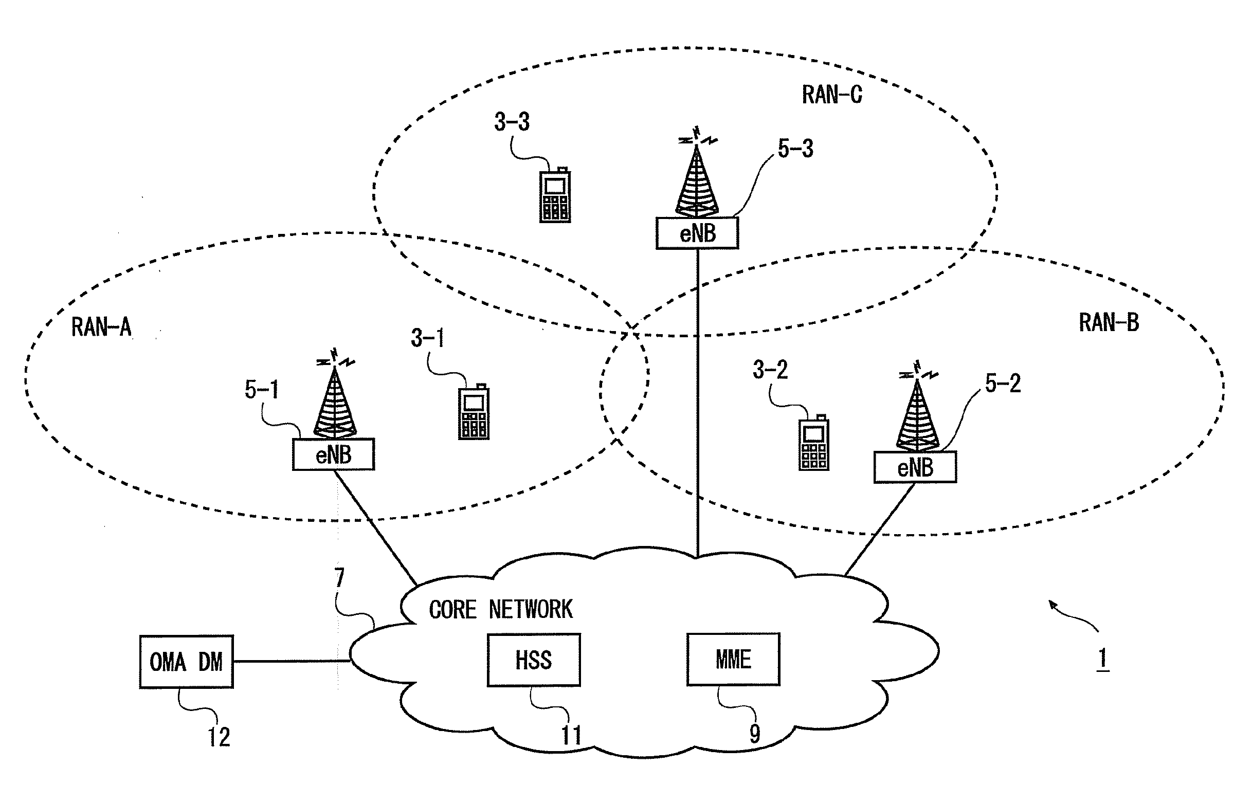
[0110]FIG. 5 shows an example timing diagram illustrating a method performed by components of the communication system 1 when carrying out paging of a mobile telephone 3 configured with an extended DRX cycle.
[0111]In this embodiment, the mobile telephone 3 obtains current time information from the respective RAN(s) it is currently using. In this example, the current time information is broadcast as part of the System Information (SI) message, as generally shown in steps S501a and S501b performed by (the base stations 5 of) RAN-A and RAN-B, respectively. The current time information allows the mobile telephone 3 to synchronise the operation of its modules to the RAN it is using. In this example, the SI message broadcast by RAN-B (at S501b) also includes an indicator (e.g. an ‘Extended DRX feature support indicator’ flag, IE, or the like) informing the mobile telephone 3 that the RAN-B supports the extended DRX cycle feature. The...
second embodiment
DRX Cycle Synchronisation Using Time of Location Registration
[0122]FIG. 6 shows an example timing diagram illustrating a method performed by components of the communication system 1 when carrying out paging of a mobile telephone 3 configured with an extended DRX cycle. This embodiment generally follows the first embodiment, however, instead of the core network selecting an arbitrary start time for the mobile telephone's 3 extended DRX cycle, a request-response procedure is carried out between the core network 7 and the RAN to derive a UE specific start time for the extended DRX cycle.
[0123]Steps S601a and S601b generally correspond to the respective SI broadcast messages at S501a and S501b described above with reference to FIG. 5. However, the messages sent at S601a (by RAN-A) and at S601b (by RAN-B) do not carry the current time information for the given RAN. Alternatively, if the messages at steps S601a / S601b include the current time information, in this embodiment the mobile tele...
third embodiment
Extended DRX Cycle without RAN Support
[0131]FIG. 7 shows an example timing diagram illustrating another method performed by components of the communication system 1 when carrying out paging of a mobile telephone 3 configured with an extended DRX cycle. This embodiment generally follows the first embodiment, however, the core network 7 provides support for the extended DRX operation without involving the RAN(s).
[0132]In this example, the mobile telephone 3 initially registers its current location with a core network entity (e.g. the MME 9) by sending, at step S703, an appropriately formatted NAS message, as explained above with reference to step S503 of FIG. 5. The NAS message (which may comprise an Attach / RAU / TAU Request) includes the mobile telephone's 3 Na and Nd parameters (i.e. the number of active and dormant SFs in its extended DRX cycle) thereby informing the core network 7 about its capability for the extended DRX cycle functionality.
[0133]When an entity in the core network ...
PUM
 Abstract
Description
Claims
Application Information
 - R&D
- Intellectual Property
- Life Sciences
- Materials
- Tech Scout
- Unparalleled Data Quality
- Higher Quality Content
- 60% Fewer Hallucinations
Browse by: Latest US Patents, China's latest patents, Technical Efficacy Thesaurus, Application Domain, Technology Topic, Popular Technical Reports.
© 2025 PatSnap. All rights reserved.Legal|Privacy policy|Modern Slavery Act Transparency Statement|Sitemap|About US| Contact US: help@patsnap.com


