Scanning module, detection device using bessel beam, detection probe, and probe type detection device

a detection module and probe technology, applied in the direction of optical radiation measurement, photometry using electric radiation detectors, instruments, etc., can solve the problems of deteriorating image quality, low accuracy of projection image, and limits of techniques, so as to improve resolution and work distance, the effect of improving the resolution

Active Publication Date: 2016-03-24
KOREA FOOD RES INST
View PDF4 Cites 12 Cited by
  • Summary
  • Abstract
  • Description
  • Claims
  • Application Information

AI Technical Summary

Benefits of technology

[0051]According to the present invention, since a Bessel beam is used to detect images, resolution is improved and a long DOF is ensured, so the working distance can be increased and the detection performance can be improved.
[0052]Further, since a DOF is long, it is possible to acquire a clear projection image of an absorber or a reflector in an object, using a projection method, when the object is positioned within the DOF.
[0053]Further, since the DOF is long, the present invention can be useful for detecting substances or objects in objects that absorbs less electromagnetic wave and has large volume or depth.
[0054]According to the present invention, since Bessel beams are used, resolution is improved and a long DOF is ensured, so the working distance can be increased and the detection performance can be improved.
[0055]Further, since it is possible to perform scanning while rotating, the present invention can be more useful for cylindrical objects.

Problems solved by technology

In general, the higher the resolution, the lower the DOF (Depth of Focus), so these techniques still have limits.
This problem takes more time to make 3D CT (Computerized Tomography) on the basis of a projection absorber image, when such depth-directional scanning is not performed, a projection image with very low accuracy is made and the quality of the image is deteriorated.
Accordingly, a working distance is considerably limited.
However, most electromagnetic beams used in the high-speed raster scanning are focused in the type of a Gaussian beam, so there are many limits in improvement of resolution and DOF, as described above.

Method used


Image

  • Scanning module, detection device using bessel beam, detection probe, and probe type detection device
  • Scanning module, detection device using bessel beam, detection probe, and probe type detection device
  • Scanning module, detection device using bessel beam, detection probe, and probe type detection device

Examples


Embodiment Construction

[0075]Hereinafter, embodiments of the present invention will be described in detail with reference to the accompanying drawings.

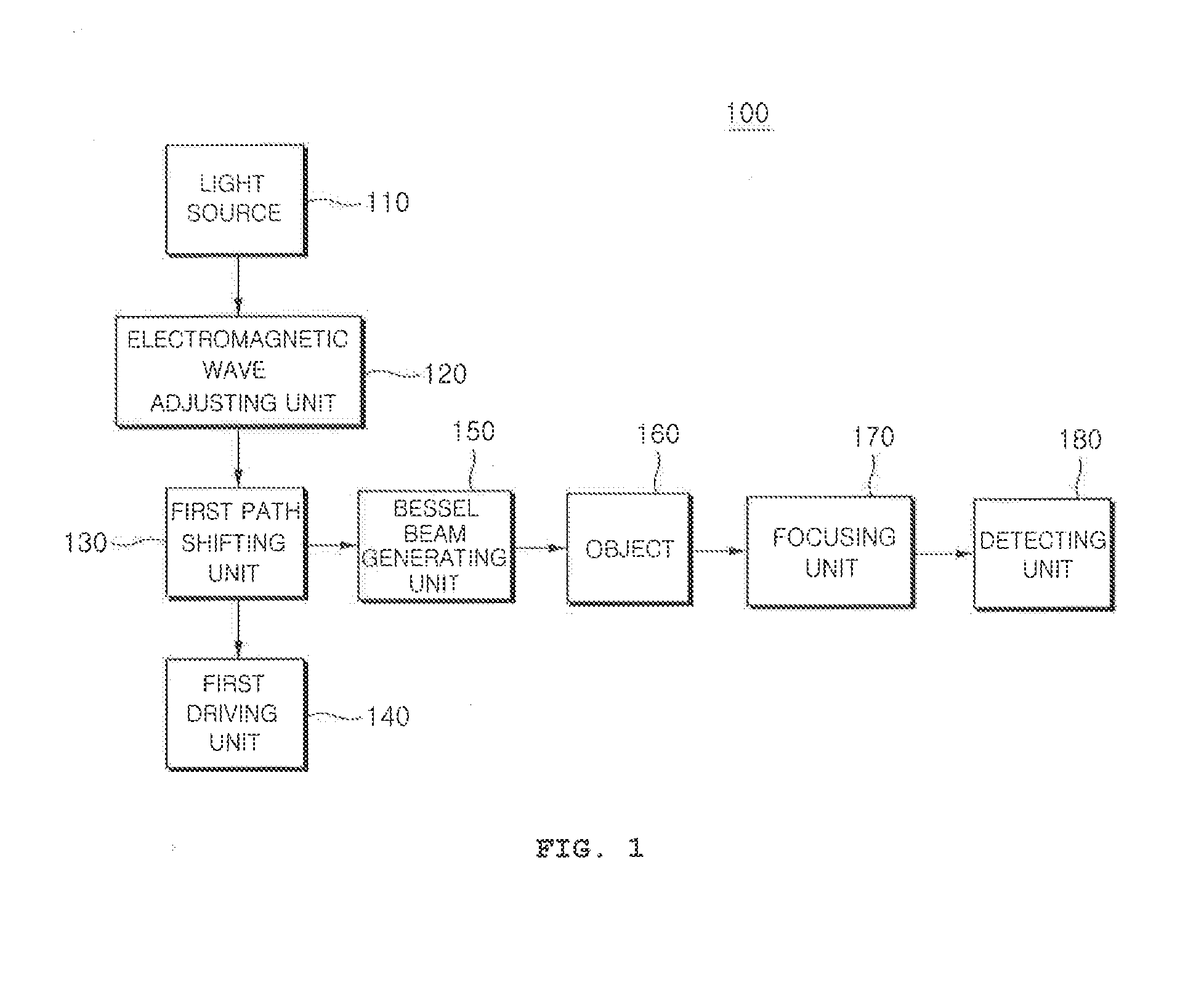
[0076]FIG. 1 is a block diagram illustrating a detection device using a Bessel beam relating to an embodiment of the present invention.

[0077]Referring to FIG. 1, a detection device 100 using a Bessel beam includes a light source 110, an electromagnetic wave adjusting unit 120, a first path shifting unit 130, a first driving unit 140, a Bessel beam generating unit 150, a object 160, a focusing unit 170, and a detecting unit 180.

[0078]A Bessel beam is an electromagnetic wave given as a zeroth-order Bessel function of the first kind in a solution set of Maxwell equation about a free space and has been known as a non-diffractive beam. The Bessel beam was first introduced by Durnin in 1987 and has axial asymmetry, in which energy is concentrated as much as a predetermined length about an axis in the shape of a needle. Since it is implemented by an optical system...


PUM


Abstract

A scanning module including first path shifting unit changing a path of an incident electromagnetic wave from a light source; a first driving unit adjusting the path of the electromagnetic wave by moving the first path shifting unit; and a Bessel beam generating unit making a Bessel beam on a portion of an object, using the electromagnetic wave with the path changed by the path shifting unit. A detection probe which includes a light source generating an electromagnetic wave; a path shifting unit changing a path of an electromagnetic wave from a light source; a Bessel beam generating unit making a Bessel beam on a portion of an object, using the electromagnetic wave with the path changed by the path shifting unit; a detecting unit detecting intensity of a wave from the object, and a housing accommodating the light source, path shifting unit, Bessel beam generating unit, and detecting unit.

Description

BACKGROUND OF THE INVENTION[0001]1. Field of the Invention[0002]An imaging method is generally used to nondestructively examine objects or substances and is largely classified into two types of an image detection type using a monochromatic light and an image detection type using a spectroscopic method. These types have advantages and disadvantages, but the image detection type using a monochromatic light is much used for a case requiring relatively high intensity such as a transmission image.[0003]2. Description of the Related Art[0004]In general, the higher the resolution, the lower the DOF (Depth of Focus), so these techniques still have limits.[0005]In particular, an optical system with high resolution has a small DOF, so it is required to scan a focal point in a depth direction of an object in order to examine the internal structure of an object having a predetermined volume in a nondestructive way. This problem takes more time to make 3D CT (Computerized Tomography) on the basi...

Claims


Application Information

Patent Timeline
Patent Type & Authority Applications(United States)
IPC IPC(8): G01J1/08G01J1/42G02B26/10
CPCG01J1/08G01J1/42G02B26/105G02B5/001
Inventor CHOI, SUNG, WOOKKIM, HYUN, JUNGLEE, NA, RICHANG, HYUN, JOOOK, GYEONG, SIK
Owner KOREA FOOD RES INST
Why Eureka
Try Eureka