Display panel and display device

a display panel and display device technology, applied in static indicating devices, instruments, non-linear optics, etc., can solve the problems of increasing the cost of manufacturing the display device and the gamut of the display device, and achieve the effect of reducing the cos

Inactive Publication Date: 2016-03-24
BOE TECH GRP CO LTD +1
View PDF13 Cites 34 Cited by
  • Summary
  • Abstract
  • Description
  • Claims
  • Application Information

AI Technical Summary

Benefits of technology

[0024]The display panel provided in this disclosure causes the birefringence of light rays to occur when they pass through an electro-optic effect layer by controlling the intensity of one or more electric fields generated by an electrode layer in the electro-optic effect layer, and thereby controls the transmittance of the light rays when they pass through the electro-optic effect layer, i.e., it controls a luminance range capable of being displayed by each sub-pixel, and adjusts the color gamut displayed by each pixel unit so as to achieve the adjustment of the color gamut displayed by the display panel. As compared with the technical solutions of adjusting the color gamut displayed by a display panel in the prior art, the display panel provided in this disclosure is capable of flexibly adjusting the color gamut displayed by the display panel within a larger range and has a lower cost.

Problems solved by technology

In the above display device, backlight sources are added therein so as to enable the display device to have different color gamuts in different display situations, which obviously increases the cost of manufacturing the display device; moreover, due to the restrictions of volume and weight of the display device, a number of the backlight sources within the display device cannot be augmented without limit, and as a result the color gamut of the display device can only be adjusted among several color gamuts (a number of the color gamuts is equivalent to a number of the backlight sources), i.e., the color gamut of the display device has a small range of adjustment.

Method used


Image

  • Display panel and display device
  • Display panel and display device
  • Display panel and display device

Examples


Embodiment Construction

[0036]Detailed description shall be provided for the embodiments of this disclosure in the following text with reference to the drawings. It should be understood that the embodiments described herein are used only for describing and explaining this disclosure, instead of limiting this disclosure.

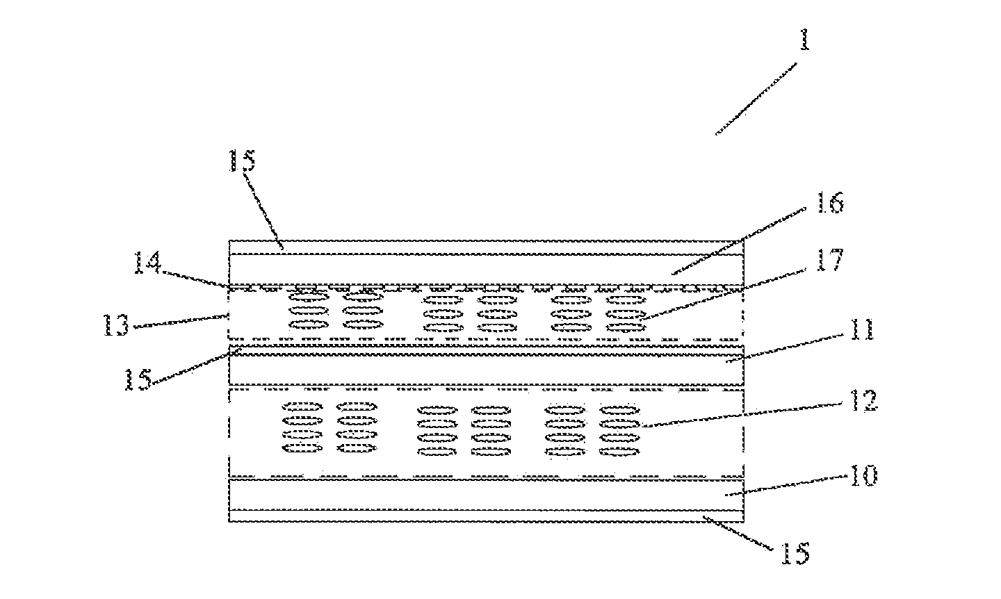
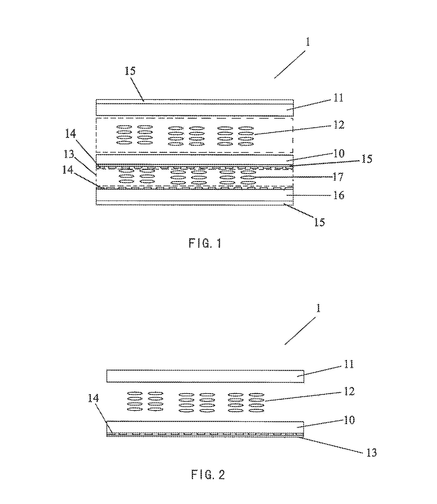
[0037]Referring to FIG. 1, FIG. 1 is a schematic view of a first embodiment of the display panel provided in this disclosure. In this embodiment, a display panel 1 comprises an array substrate 10, a color film substrate 11, a first liquid crystal layer 12 disposed between the array substrate 10 and the color film substrate 11, an electro-optic effect layer 13 and an electrode layer 14. The electrode layer 14 is used to generate an electric field in the electro-optic effect layer 13, and it can be arranged on both sides of the electro-optic effect layer 13 as shown in FIG. 1, or on one side of the electro-optic effect layer 13 as shown in FIG. 2; the electro-optic effect layer 13 is arranged ...


PUM

PropertyMeasurementUnit
electric fieldaaaaaaaaaa
birefringenceaaaaaaaaaa
Kerr effectaaaaaaaaaa

Abstract

This disclosure relates to a display panel and a display device, said display panel comprising an array substrate, a color film substrate and a first liquid crystal layer disposed between the array substrate and the color film substrate, said display panel further comprising an electro-optic effect layer and an electrode layer disposed on one side or on both sides of the electro-optic effect layer; said electrode layer is used to generate an electric field in said electro-optic effect layer; said electro-optic effect layer is disposed on an outer side of the array substrate or on an outer side of the color film substrate, for causing birefringence of light rays to occur under the effect of said electric field when they pass through said electro-optic effect layer. Said display panel is capable of flexibly adjusting the color gamut displayed by the display panel within a larger range and has a lower cost.

Description

RELATED APPLICATIONS[0001]The present application claims the benefit of Chinese Patent Application No. 201410490296.X, filed Sep. 23, 2014, the entire disclosure of which is incorporated herein by reference.TECHNICAL FIELD[0002]This disclosure relates to the technical field of liquid crystal display, and specifically to a display panel and a display device.BACKGROUND ART[0003]Color gamut is the sum total of all possible colors generated by a technical system. In a display device, color gamut is one of the important indexes for evaluating the display quality. With the development of techniques and the constant changes in the need of use, people now require display devices to have not only larger color gamut, but also different color gamuts in different display situations.[0004]For an existing display device, it is generally enabled to have different color gamuts in different display situations by using a method as follows, i.e., installing in the display device a plurality of backlig...

Claims


Application Information

Patent Timeline
Patent Type & Authority Applications(United States)
IPC IPC(8): G02F1/1343G02F1/1335
CPCG02F1/134309G02F2001/134345G02F1/13439G02F1/133514G02F1/1393G02F1/13471
Inventor XU, JUN
Owner BOE TECH GRP CO LTD
Why Eureka
Try Eureka