
Shadow suppression in ultrasound imaging

a technology of ultrasound imaging and shadow suppression, applied in ultrasonic/sonic/infrasonic image/data processing, instruments, etc., can solve the problems of ultrasound shadowing, poor transmission of acoustic energy, shadowing, etc., and achieve the effect of reducing or removing shadows

Active Publication Date: 2016-03-31
SIEMENS MEDICAL SOLUTIONS USA INC
View PDF11 Cites 13 Cited by
  • Summary
  • Abstract
  • Description
  • Claims
  • Application Information

AI Technical Summary

Benefits of technology

This patent describes a new invention and its advantages. The invention is outlined in the claims, and there are no limitations on those claims. The technical effects of the invention are discussed below.

Problems solved by technology

Ultrasound shadowing is caused by poor transmission of acoustic energy through or high reflection from scattering objects.
As another example, shadowing occurs due to poor transducer contact.
When imaging using steered spatial compounding, shadows create fork-like image artifacts since the shadows tend to weigh down the compounded image mean in the shadowing locations.
Anatomy information may be lost due to this reduction.
However, proper spatial image registration may not be achieved, resulting in poor shadow identification.

Method used


Image

  • Shadow suppression in ultrasound imaging
  • Shadow suppression in ultrasound imaging
  • Shadow suppression in ultrasound imaging

Examples


Embodiment Construction

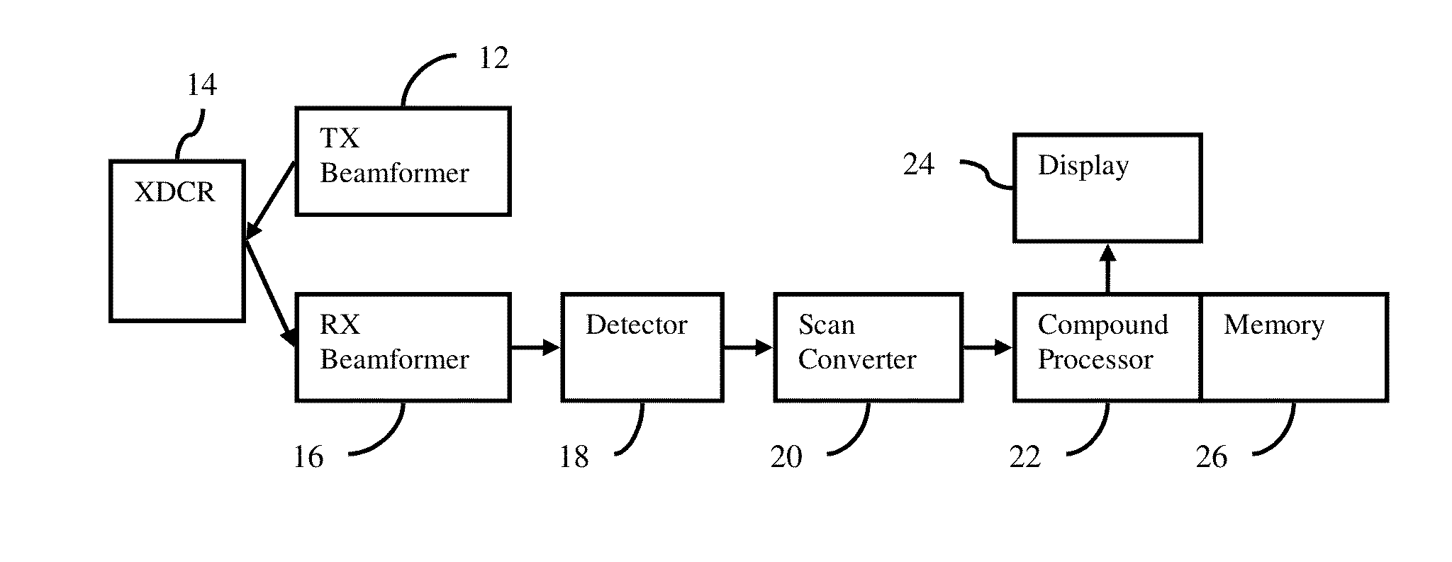
[0020]The received image data of a single frame is transformed, and a projection image is generated using knowledge of the transmit imaging angle. The transformed projection image is then used to generate weights. Knowledge of the transmit angle direction and corresponding transform projection images are used to help determine the steered spatial compounding image weights. The weights are used to compensate the original received image data. This approach does not require image registration for shadow reduction as shadows are suppressed by weighting the original images using their respective projection images. The shadow reduction weights are created on a per frame basis even for steered compounding.

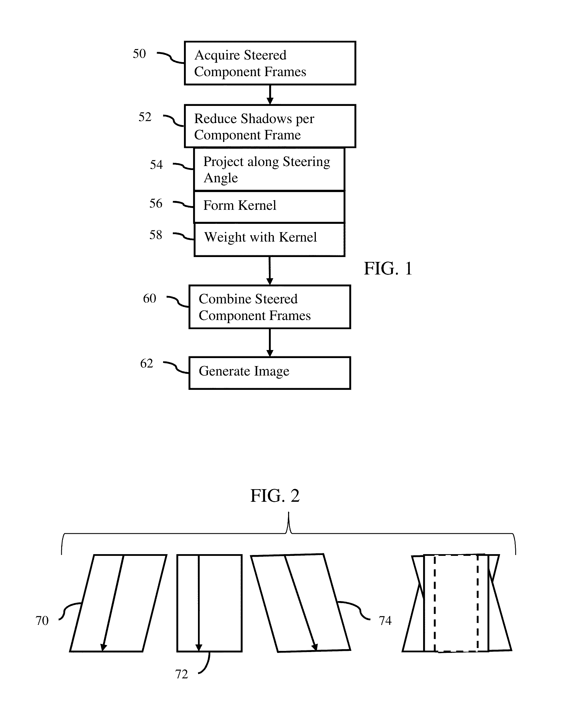
[0021]FIG. 1 shows one embodiment of a method for shadow suppression in ultrasound imaging. The embodiments are described below in the context of steered spatial compounding. In other embodiments, shadow suppression is provided for single or multiple frame imaging modalities, such as B-mo...


PUM


Abstract

Shadow suppression is provided in ultrasound imaging, such as in steered spatial compounding. Using a transform or other approach, the data of a frame of data along the steering direction is projected. The projection is used to determine weights. The frame is weighted with the projection-based weights, reducing or removing shadows based on the one frame rather than based on registration with other frames. In the steered spatial compounding example, a compounded frame with independently shadow suppressed component frames may have little or no fork-like image artifacts due to shadowing.

Description

BACKGROUND[0001]The present invention relates to shadow suppression in ultrasound imaging.[0002]Ultrasound shadowing is caused by poor transmission of acoustic energy through or high reflection from scattering objects. For example, dense tissue may cause a shadow obscuring return from tissue separated from the transducer by the dense tissue. As another example, shadowing occurs due to poor transducer contact. The shadows themselves appear as areas of low echogenicity that are typically highly correlated with the direction of transmission.[0003]Shadows may occur in various modes of imaging, such as occurring in steered spatial compounding. One component frame of data is acquired by scanning along scan lines at one angle relative to a transducer. A second component frame of data is acquired by scanning along scan lines at a different angle. The frames of detected data are compounded together and displayed as an image. When imaging using steered spatial compounding, shadows create fork...

Claims


Application Information

Patent Timeline
IPC IPC(8): A61B8/08A61B5/00A61B8/00A61B8/14
CPCA61B8/5269A61B8/5253A61B5/7257A61B8/5207A61B8/4483A61B8/145A61B8/463A61B8/13G01S15/8977G01S15/8995G01S7/52033
Inventor DUNCAN, DAVID, P.MENON, MANOJ, G.
Owner SIEMENS MEDICAL SOLUTIONS USA INC
Learn More