Hybrid linear actuator controlled hydraulic cell stretching

a technology of hydraulic cell and linear actuator, which is applied in the direction of apparatus sterilization, biomass after-treatment, laboratory glassware, etc., to achieve the effect of prolonging uninterruptible duty cycles, being easily manipulable/altered, and being easily derivatizabl

Active Publication Date: 2016-03-31
BOARD OF SUPERVISORS OF LOUISIANA STATE UNIV & AGRI & MECHANICAL COLLEGE
View PDF8 Cites 2 Cited by
  • Summary
  • Abstract
  • Description
  • Claims
  • Application Information

AI Technical Summary

Benefits of technology

[0007]As will become apparent with further description below the disclosed cell flexing device has several advantages over the existing devices on the market for flexing cells in vitro. First, the disclosed cell flexing device is preferably self-contained, as regards to at least fluid force, and does not rely on an external vacuum source to provide motive force, as is common in practice today. The disclosed system can be configured to operate independent of a desktop computer controller if necessary, being configured to be controlled via an IPAD or other handheld or mobile device, with the input and the output communications maintained by direct wire connection or by radiowave (e.g. WiFi), or with integrated electrical controls, including memory, CPU, input and output. The disclosed cell flexing device will also preferably incorporate a battery-backup system to permit an end user to maintain the cell stretching activity of the device during power outages or while moving the device within the laboratory environment. This allows the user to perform month(s) or year(s) long continuous experiments without out stopping the cell stretching activity of the device.
[0008]Second, a fluid coupling of the piston to the flexible membranes permits precise application of a wide range and fine gradation of user controllable strain, currently unavailable in the art. The captive hybrid linear actuator drive is powerful, reliable, and capable of prolonged uninterruptible duty cycles. The first disclosed embodiment has functioned for over a year of continuous operation. For this embodiment, the resolution of the actuator is at 63 μm per step, and the final membrane displacement of the flexible membrane in the well is a function of the actuator lead screw / rod stroke and the piston area relative to the total membrane area. Depending on the intended application of the device, these parameters can be easily manipulated / altered by one of ordinary skill in the art by changing the design or function of the linear actuator and / or by modifying the dimensions of the cylinder / piston assembly. During the flexing regimen, the movement (amplitude and frequency) of the linear actuator, and thus the membrane is regulated by user-defined commands set up in the software.
[0009]Third, unlike existing devices on the market, the linear actuator system can run a single step stretch (i.e. from point A to point B) and hold at that position for a preset period of time. This allows for the direct in vivo imaging of biosensor activation in response to a single displacement force.
[0010]Fourth, the substrate is easily derivatizable silicon, which permits coupling a wide range of ligands to the substratum for cell adhesion.
[0011]Fifth, the production cost of the hydraulic cell flexing device is very economical. The first embodiment materials cost is less than $800 / unit. The hydraulic cell flexing device is also scalable from the one to three wells in the first embodiment. Well plates ranging from, for example, a single well, to 12 wells to at least 384 wells are possible, allowing the system to be used in high throughput screening assays.
[0012]Sixth, unlike existing devices, this hydraulic cell flexing device is capable of multiplex flexing within the same apparatus. That is, the rate and degree of flexing between multiple groups or rows of flexing wells can be differentially regulated. This can be accomplished via the incorporation of multiple drive modules in a single apparatus, or the incorporation of multiple pressure limiting valves / pressure regulators for a single or multiple drive module(s). Using the multiple drive module approach, multiple flexing regimens to be applied to different groups of cells during the same experiment period on the same apparatus, with the reliability and fine control offered by separate drive modules for each hydraulic pressure line. Using the multiple pressure regulator approach, multiple flexing regimens to be applied to different groups of cells during the same experiment period on the same apparatus may also be achieved, with multiple pressure lines from a single drive module, and a pressure regulator on most, or all, or all but one pressure line. Each of these approaches will save users both the cost of materials and experimentation time, and dramatically increases the functionality available to users.

Problems solved by technology

Second, a fluid coupling of the piston to the flexible membranes permits precise application of a wide range and fine gradation of user controllable strain, currently unavailable in the art.

Method used


Image

  • Hybrid linear actuator controlled hydraulic cell stretching
  • Hybrid linear actuator controlled hydraulic cell stretching
  • Hybrid linear actuator controlled hydraulic cell stretching

Examples


Embodiment Construction

[0042]The present invention will be understood by reference to the following detailed description, which should be read in conjunction with the appended drawings. It is to be appreciated that the following detailed description of various embodiments is by way of example only and is not meant to limit, in any way, the scope of the present invention.

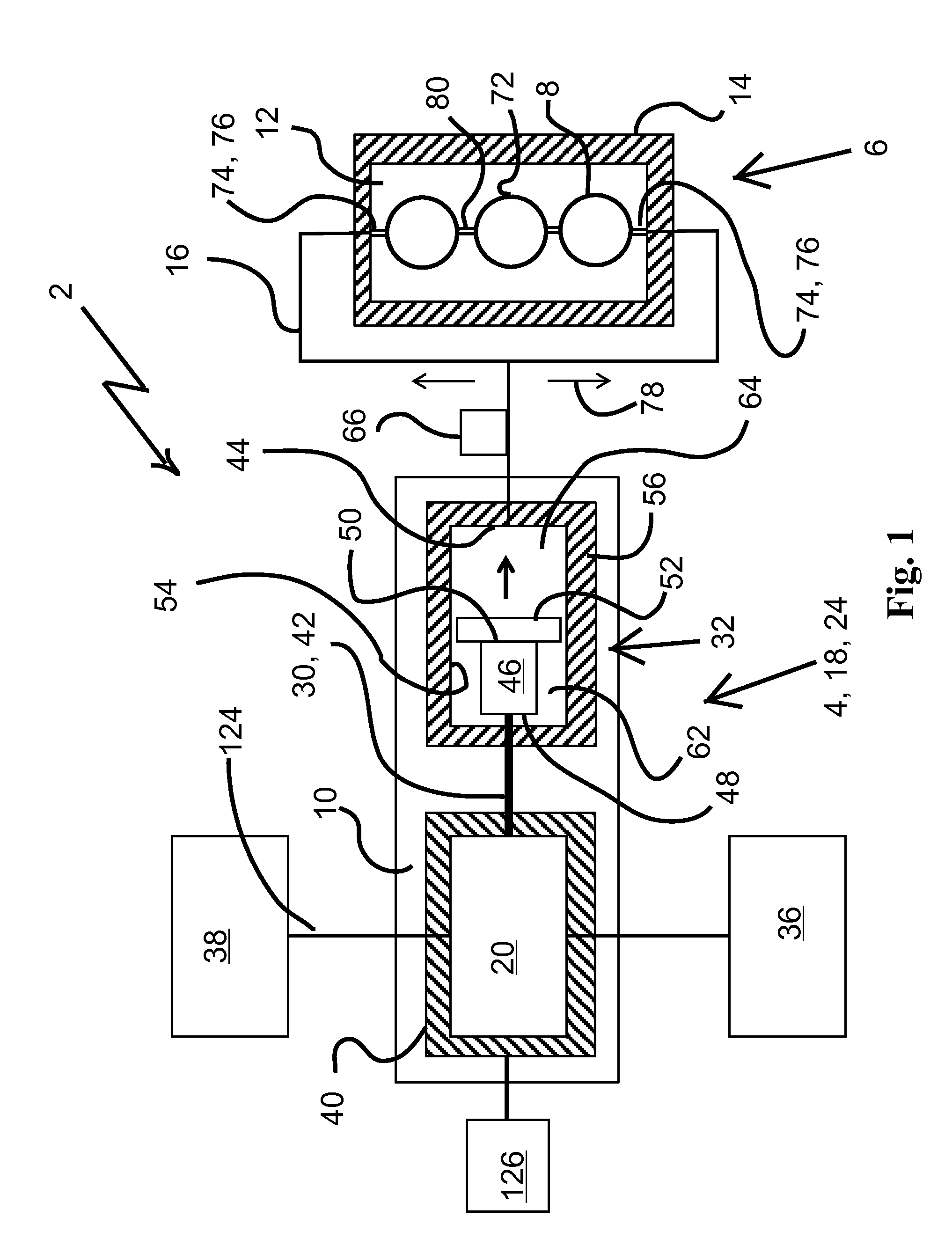
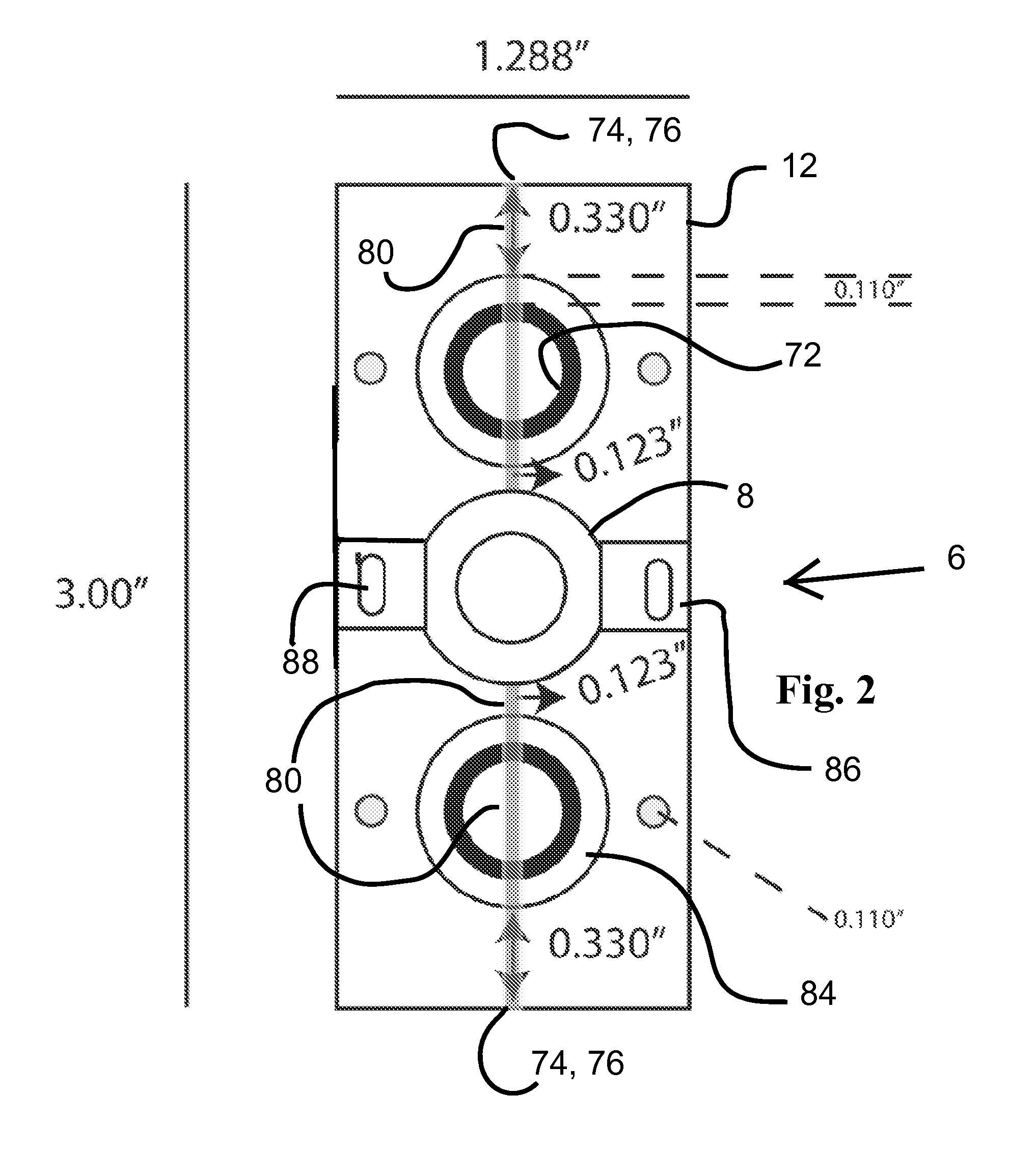
[0043]Turning now to FIG. 1, a brief description concerning the various components of the present invention will now be briefly discussed. As can be seen in this embodiment, the hydraulic cell flexing device 2 is comprised of a source of variable pressured hydraulic fluid 4 and a flexing chamber 6 comprising one or more cell wells 8. The source of variable pressured hydraulic fluid 4 and the flexing chamber 6 are both preferably mounted on a single foundation plate 10.

[0044]FOUNDATION PLATE—In the embodiment shown a foundation plate 10 measures approximately 11.5″×3″×0.5″, though this can vary based on the spacing of the constituent parts ...


PUM

PropertyMeasurementUnit
lengthaaaaaaaaaa
distanceaaaaaaaaaa
displacementaaaaaaaaaa

Abstract

A hydraulic cell stretching device comprising a source of variable pressured hydraulic fluid hydraulically coupled to a flexing chamber. The flexing chamber has at least one cell well. The cell well has a membrane subjected to the variable pressured hydraulic fluid.

Description

CROSS REFERENCE TO RELATED APPLICATIONS / PRIORITY[0001]This invention claims priority to U.S. Provisional Patent Application No. 62 / 055,168 filed on Sep. 25, 2014. Provisional Patent Application No. 62 / 055,168 is incorporated into the present disclosure as if fully restated herein.STATEMENT REGARDING FEDERALLY SPONSORED RESEARCH OR DEVELOPMENT[0002]The invention was under a contract with an agency of the United States Government. The name of the U.S. Government agency is NIH / NIDDK and the Government grant / contract number is DK077860. The United States Government has certain rights in this invention.FIELD OF THE INVENTION[0003]The present invention relates to an electrotechnical / hydraulic cell flexing device that is capable of cyclic, high-resolution, and high gradation of stretching of a flexible membrane that carries the cell(s).BACKGROUND OF THE INVENTION[0004]Many cells in, inter alia, the mammalian body, including those in the circulatory system, undergo periodic flexing in vivo....

Claims


Application Information

Patent Timeline
Patent Type & Authority Applications(United States)
IPC IPC(8): B01L3/00C12M1/00C12M1/12C12M1/36C12M3/06F15B15/10F15B15/14
CPCB01L3/502761F15B15/14F15B15/10C12M25/04C12M47/00C12M41/48B01L2200/0663C12M23/16B01L3/502715B01L3/502738B01L3/50273B01L2400/0478C12M43/00C12M23/12C12M35/04
Inventor MCCARTHY, KEVIN, JOHNWASSENHOVE-MCCARTHY, DEBORAH, JANE
Owner BOARD OF SUPERVISORS OF LOUISIANA STATE UNIV & AGRI & MECHANICAL COLLEGE
Why Eureka
Try Eureka