
Controller for vehicle transmission

a technology for controlling the transmission and vehicle, which is applied in the direction of gearing control, gearing elements, gearing, etc., can solve the problems of increasing shock in the change, limited operation point of the engine with high efficiency, and insufficient driving force, so as to achieve large acceleration of the vehicle

Active Publication Date: 2016-03-31
TOYOTA JIDOSHA KK
View PDF5 Cites 9 Cited by
  • Summary
  • Abstract
  • Description
  • Claims
  • Application Information

AI Technical Summary

Benefits of technology

The invention is a controller for a vehicle transmission that prevents or suppresses shocks and decreases in durability of the clutch when changing between different transmission paths. The controller determines whether the change shift is allowed by checking the speed ratio of the first transmission mechanism and the rotation speed difference in the clutch. It also sets a rotation speed difference limit to prevent shocks and decrease in clutch durability during the change shift. The controller narrows the width of the change speed ratio region as the input torque increases to prevent excessive heat and wear on the clutch. Overall, the invention improves the reliability and durability of the vehicle transmission.

Problems solved by technology

When the engine is operated, an operating point at which the engine has a high efficiency is limited.
As a result, there is a possibility that a shock in the change increases, driving force becomes insufficient after the change or the engine rotation speed increases more than necessary.
Therefore, there is an inevitable response delay at the time of hydraulic control, and there is a limit in trackability of an actual speed ratio to a target value of the speed ratio.
As a result, friction increases at the time when the friction materials of the clutch engage with each other, so the durability of the clutch decreases.
In addition, an engagement shock also increases at the time when the clutch is engaged.

Method used


Image

  • Controller for vehicle transmission
  • Controller for vehicle transmission
  • Controller for vehicle transmission

Examples


first control example

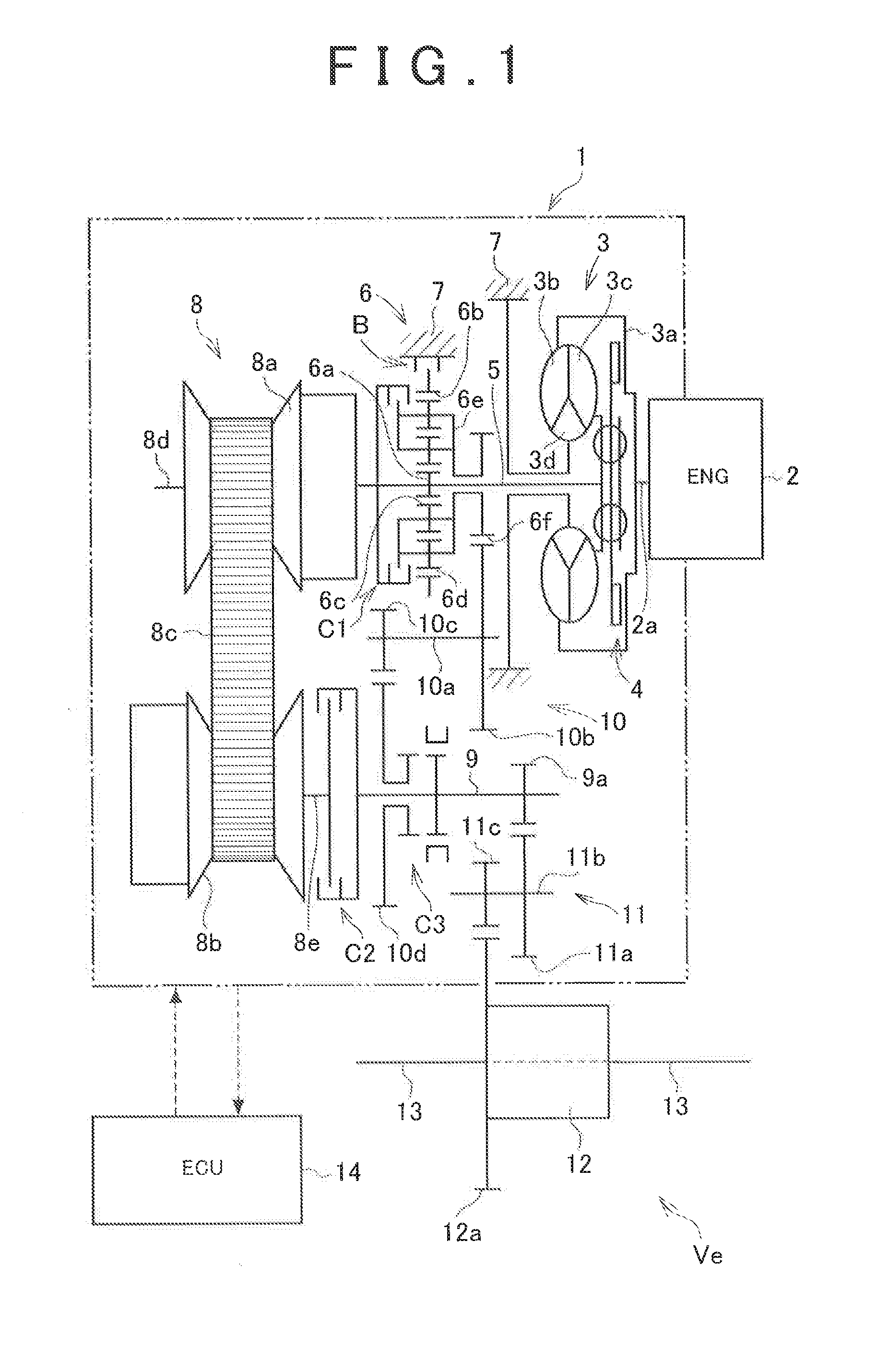
[0067]FIG. 3 is a flowchart for illustrating a first control example that is executed by the controller according to the invention and basic details of control of the invention. A routine shown by the flowchart is repeatedly executed at predetermined short time intervals. In FIG. 3, initially, it is determined whether it is required to change the power transmission path between first transmission path including the CVT 8 and the second transmission path including the gear train 10. That is, it is determined whether the change shift is required (step S1). This is control that is generally executed in conventional shift control, and is determined on the basis of the vehicle speed or the output shaft rotation speed of the output shaft 9 and the accelerator operation amount or a throttle opening degree. For example, it may be determined whether the change shift is required on the basis of a map or shift line chart set in association with the output shaft rotation speed and the accelerat...

second control example

[0077]FIG. 6 is a flowchart for illustrating a second control example that is executed by the controller according to the invention. The second control example is a control example in which, on the basis of the above-described first control example, a threshold in setting the change speed ratio region is corrected and a guard timer (backup timer), or the like, in determining whether to carry out a change shift is provided. This second control example shows an example in the case of carrying out the change shift from the second transmission path including the gear train 10 to the first transmission path including the CVT 8. In FIG. 6, initially, it is determined whether the operating state of the automatic transmission 1 is in a fixed shift region in the shift line chart (step S11). This determination may be carried out on the basis of the output shaft rotation speed or the vehicle speed, and the accelerator operation amount or the throttle opening degree. For example, it may be dete...


PUM


Abstract

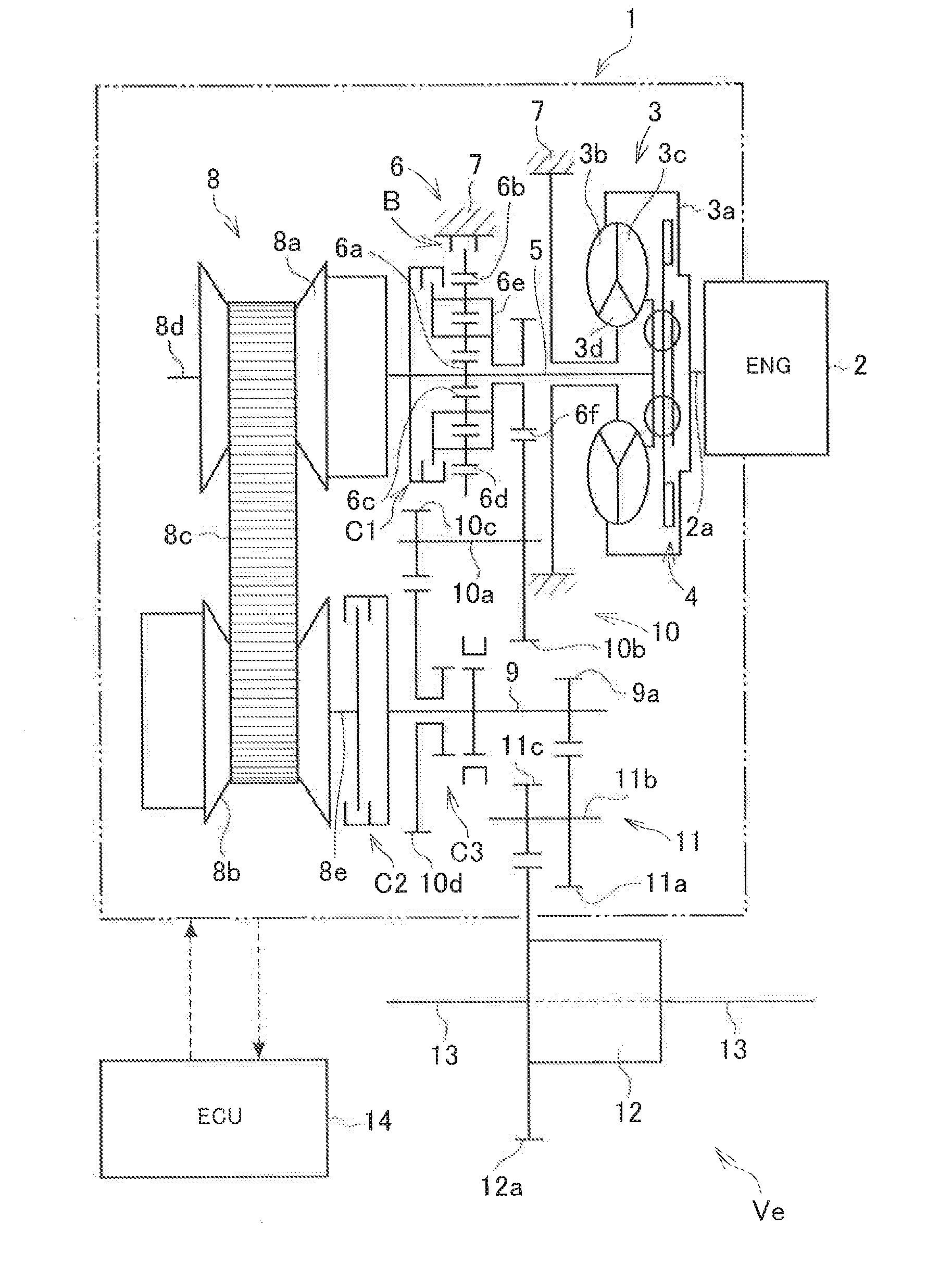
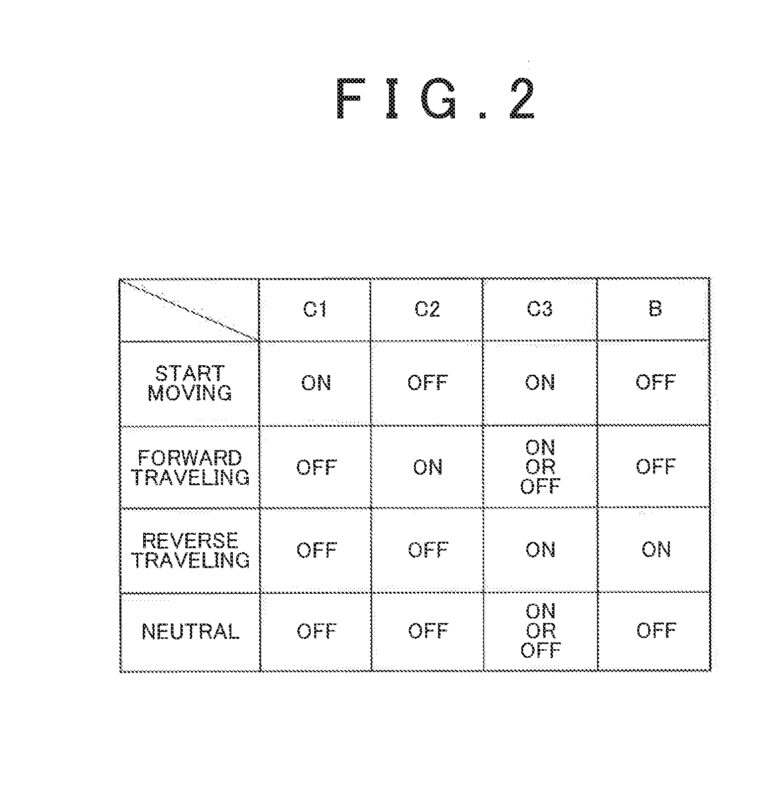
A controller for a vehicle transmission in which a first transmission path including a first transmission mechanism that is able to continuously change its speed ratio and a second transmission path including a second transmission mechanism having a set speed ratio different from that of the first transmission mechanism are provided in parallel with each other between an input shaft to which torque is input from a driving force source of a vehicle and an output shaft that outputs torque to an output member, the vehicle transmission carrying out transmission of power between the input shaft and the output shaft via one of the first transmission path and the second transmission path, includes: performing means for carrying out a change shift for changing a path of the transmission of power between the first transmission path and the second transmission path by engaging a predetermined clutch mechanism; and setting means for setting a change speed ratio region that defines a range of a speed ratio of the first transmission mechanism such that a rotation speed difference between engagement members of the clutch mechanism, which are engaged with each other in carrying out the change shift, is smaller than or equal to a predetermined value. When a speed ratio outside the change speed ratio region is set in the first transmission mechanism, the change shift is not carried out.

Description

CROSS-REFERENCE TO RELATED APPLICATIONS[0001]This application is a national phase application of International Application No. PCT / JP2013 / 061316, filed Apr. 16, 2013, the content of which is incorporated herein by reference.TECHNICAL FIELD[0002]The invention relates to a controller for a vehicle transmission in which two power transmission paths having different speed ratios are provided in parallel with each other between an input shaft and an output shaft.[0003]BACKGROUND ART[0004]A general engine that is used as a driving force source for a vehicle has such a characteristic that the output torque increases with an increase in rotation speed. In contrast, driving force that is required of a vehicle is usually relatively large in the case of a low vehicle speed, and is relatively small in the case of a high vehicle speed. That is, when the vehicle that uses the engine as a driving force source travels, torque having an opposite tendency to the output characteristic of the engine is...

Claims


Application Information

Patent Timeline
IPC IPC(8): F16H61/662F16H37/02
CPCF16H37/022F16H61/662F16H2061/6603F16H61/66259F16H2037/026F16H2059/465F16H61/00F16H61/12F16H61/16
Inventor KIMURA, MOTONORIINOUE, DAISUKEAYABE, ATSUSHIISHIKAWA, SHUHEIKONDO, HIROKIHINO, AKIRAMATSUO, KENJISHIMAZU, TAKURO
Owner TOYOTA JIDOSHA KK
Learn More