Supercharge Your Innovation With Domain-Expert AI Agents!

Pointing device fitting structure and pointing device

a technology of pointing device and fitting structure, which is applied in the direction of mechanical control devices, instruments, manual control with single controlling member, etc., can solve the problems of deteriorating keyboard appearance, pointing stick deviating from the central axis line of the insertion hole of the stick housing, and increasing the cost of the product per se, so as to achieve low product profile and facilitate assembly

Active Publication Date: 2016-03-31
MINEBEAMITSUMI INC
View PDF4 Cites 1 Cited by
  • Summary
  • Abstract
  • Description
  • Claims
  • Application Information

AI Technical Summary

Benefits of technology

The technical effect of this patent text is that it provides a pointing device that is easy to assemble, accurately positions the frame and stick, and has a low profile for the product.

Problems solved by technology

It is not preferable to strictly manage and control the dimensional tolerance for each component and the assembly tolerance between the respective components in such a manner, because the cost of the product per se is increased by performing such strict management.
In such a configuration, however, there is a fear that the pointing stick deviates from the central axis line of the stick insertion hole of the housing.
In such a case, the top end of the pointing stick projects out from the keyboard operation surface in a state that the pointing stick is extremely close to only some of the operation keys arrayed on the housing, and the appearance of the keyboard deteriorates.
In addition to that, there is a fear that direction(s) in which the pointing stick cannot be tilted sufficiently, during an operation of the pointing stick, arise(s) due to an interference between the pointing stick and a portion of the housing, and an operation of the pointing stick is impeded.
Further, even if it is supposedly possible to assemble every component without causing such deviation as described above, the following problems may occur.
That is, because a gap is formed at a somewhat large size between the pointing stick and the stick insertion hole of the housing, some foreign substances may come into the housing via the gap to impede keyboard operation, and / or foreign substances may be caught in the gap to make it impossible to operate the pointing stick appropriately.
Such problems as mentioned above are particularly noticeable with notebook PCs in considerably small sizes, which are convenient for portage, which are manufactured in large numbers especially in recent years, and which are provided with a pointing stick.
This is because such small size notebook PCs have narrower intervals between the respective operation keys on the keyboard due to the construction of the PCs, and space for disposing the pointing stick is also small.

Method used


Image

  • Pointing device fitting structure and pointing device
  • Pointing device fitting structure and pointing device
  • Pointing device fitting structure and pointing device

Examples


Embodiment Construction

[0018]Hereinbelow, an explanation will be made on a pointing device fitting structure related to each embodiment of the present teaching. The pointing device fitting structure related to each embodiment of the present teaching is applied to a notebook PC which includes a pointing stick between operation keys of the keyboard. In the drawings, the sizes, thicknesses, and dimensions of components or parts related to the embodiments and modified embodiment are depicted exaggeratedly for easy understanding of the present teaching. Further, in the following explanation, the term “upper side” or “lower side” of an object means the “upper side” or the “lower side” of the object depicted in drawings.

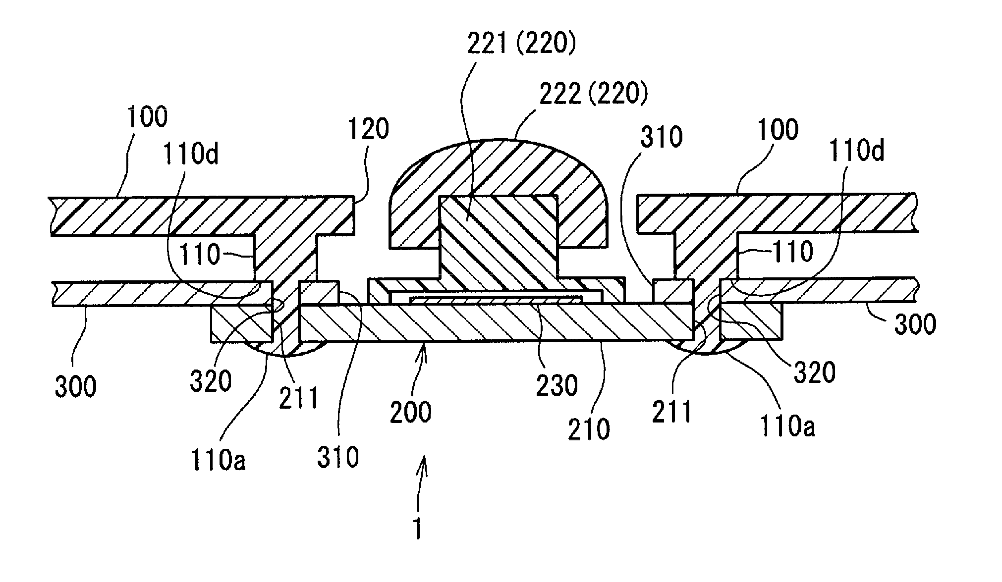
[0019]First, an explanation will be made on a pointing device fitting structure 1 related to a first embodiment of the present teaching. FIG. 1 is a cross-sectional view depicting the pointing device fitting structure 1 related to the first embodiment of the present teaching.

[0020]The pointing de...


PUM


Abstract

There is provided a pointing device fitting structure. The pointing device fitting structure includes a frame provided with a projecting portion, and a support member to which a pointing stick is attached. The frame is fixed to the support member via the projecting portion.

Description

CROSS REFERENCE TO RELATED APPLICATION[0001]The present application claims priority from Japanese Patent Application No. 2014-199467 filed on Sep. 29, 2014, and titled “POINTING DEVICE FITTING STRUCTURE AND POINTING DEVICE”, the disclosure of which is incorporated herein by reference in its entirety.BACKGROUND OF THE INVENTION[0002]1. Field of the Invention[0003]The present teaching relates to pointing device fitting structures for pointing device which includes a pointing stick. The pointing stick has a manipulation portion, and cursors can be moved (manipulated) by tilting the manipulation portion of the pointing stick. The present teaching relates, in particular, to pointing device fitting structures and a pointing device which are used for notebook-type computers (notebook personal computer (PC), laptop PC), game consoles (game machines), and the like.[0004]2. Description of the Related Art[0005]As notebook PCs spread, a pointing stick comes into use for moving a cursor on a dis...

Claims


Application Information

Patent Timeline
Patent Type & Authority Applications(United States)
IPC IPC(8): G06F3/0338
CPCG06F3/0338G05G9/047G05G2009/04762G06F3/0213
Inventor MORI, MASAO
Owner MINEBEAMITSUMI INC
Features
  • R&D
  • Intellectual Property
  • Life Sciences
  • Materials
  • Tech Scout
  • Unparalleled Data Quality
  • Higher Quality Content
  • 60% Fewer Hallucinations
Learn More