Printed Timer Label

Inactive Publication Date: 2016-03-31
THIN FILM ELECTRONICS ASA
View PDF10 Cites 3 Cited by
  • Summary
  • Abstract
  • Description
  • Claims
  • Application Information

AI Technical Summary

Benefits of technology

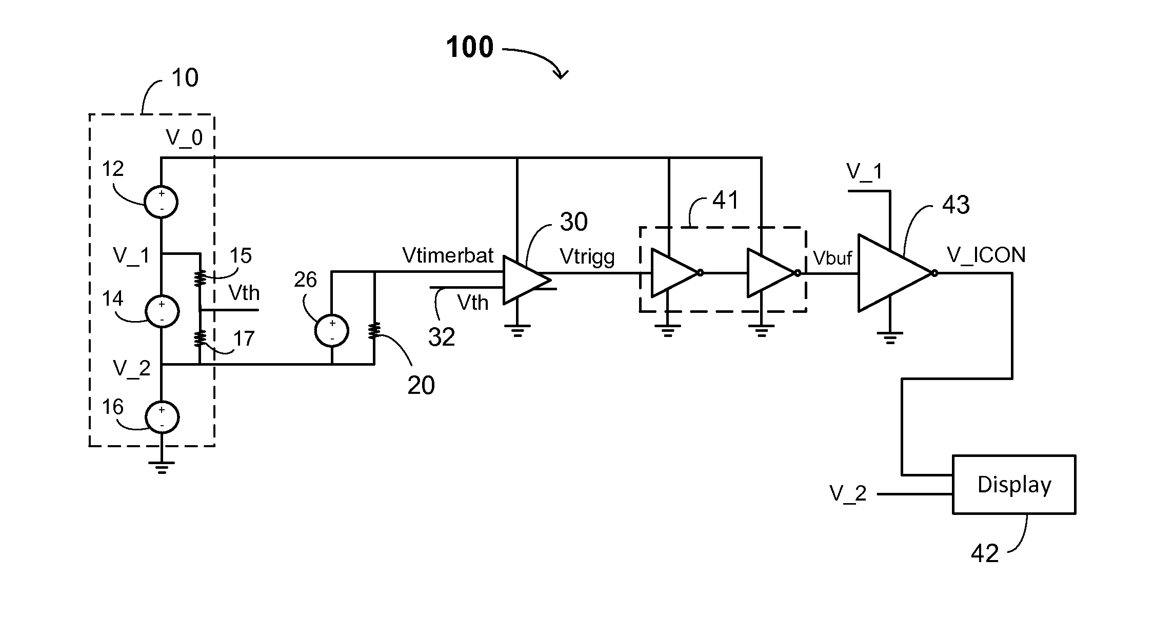
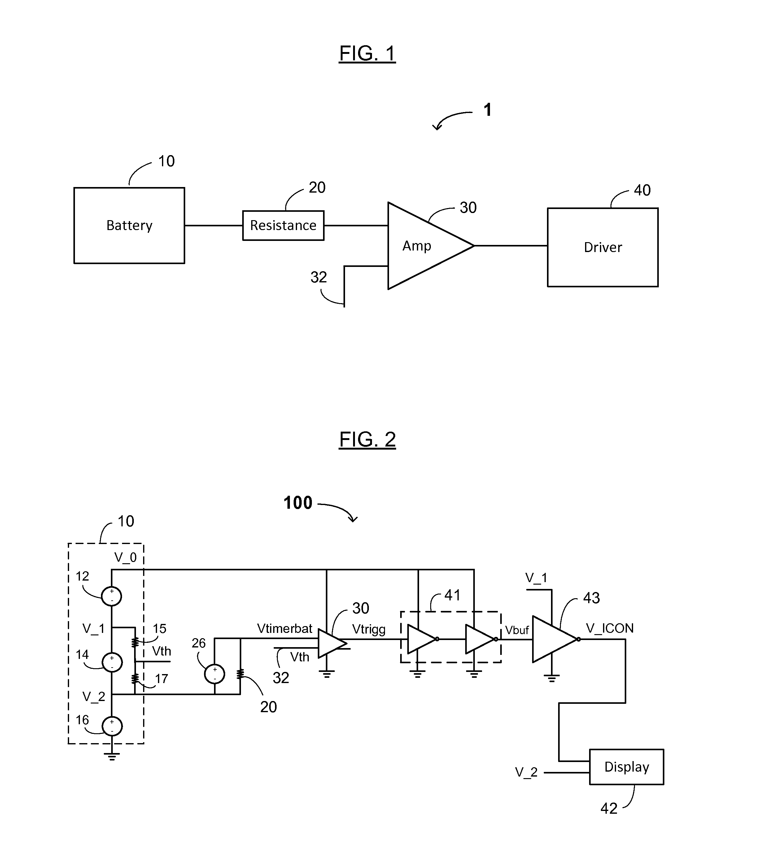
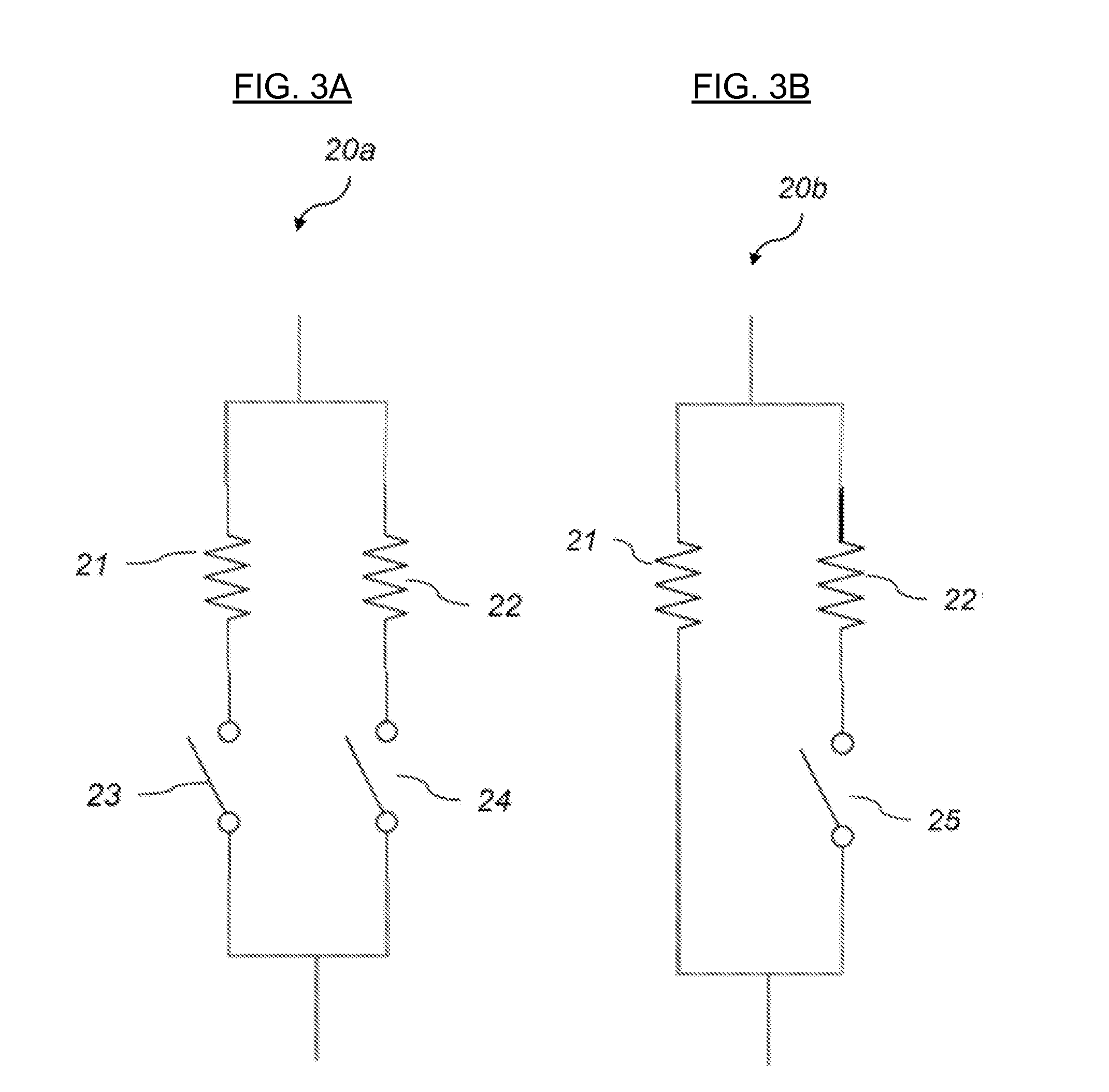
The present invention is about a printed timer label that has a battery, a load resistance, and a printed voltage comparison circuitry. This label can be printed on a label, making it cost-effective and suitable for large-scale manufacturing. The label also includes one or more electronic components that serve as a load resistance for the battery. The size of the load resistance can affect the discharge time of the battery. This invention describes a way to create a printed timer label that is efficient and economical.

Problems solved by technology

The use of an integrated circuit however has some disadvantages in such application.
This makes such timer label complicated and expensive to produce.

Method used


Image

  • Printed Timer Label
  • Printed Timer Label
  • Printed Timer Label

Examples


Embodiment Construction

[0025]Reference will now be made in detail to various embodiments of the invention, examples of which are illustrated in the accompanying drawings. While the invention will be described in conjunction with the following embodiments, it will be understood that the descriptions are not intended to limit the invention to these embodiments. On the contrary, the invention is intended to cover alternatives, modifications and equivalents that may be included within the spirit and scope of the invention. Furthermore, in the following detailed description, numerous specific details are set forth in order to provide a thorough understanding of the present invention. However, it will be readily apparent to one skilled in the art that the present invention may be practiced without these specific details. In other instances, well-known methods, procedures, components, and materials have not been described in detail so as not to unnecessarily obscure aspects of the present invention.

[0026]The tec...


PUM


Abstract

A printed timer label including a substrate, a printed battery on the substrate, a printed load resistance configured to control a discharge time of the printed battery, and printed voltage comparison circuitry connected to the printed battery and configured to provide an output signal depending on the output voltage of the printed battery relative to a predetermined threshold value.

Description

CROSS REFERENCE TO RELATED APPLICATION[0001]This application claims the benefit of U.S. Provisional Patent Application No. 62 / 058,020, filed on Sep. 30, 2014, incorporated herein by reference as if fully set forth herein.FIELD OF THE INVENTION[0002]The present disclosure generally relates to the field(s) of printed electronic circuitry. More specifically, embodiments of the present invention pertain to a printed timer circuit, especially to a printed timer circuit using a voltage differential.DISCUSSION OF THE BACKGROUND[0003]The development of technology for printed electronic circuits enable printed electronic devices such as smart labels. The use of printing of functional inks allows the introduction of electronic functionality to labels and other disposable products in a cheap and large scale manufacturing manner.[0004]One application for this technology is timer labels in which an irrevocable activation of the timer starts a countdown and which in some way indicates the end of ...

Claims


Application Information

Patent Timeline
IPC IPC(8): H05K1/18H01M10/42
CPCH05K1/189H01M10/425H05K1/182H01M10/0436H01M10/052H01M10/44H01M10/488H01M6/40H01M6/505H05K1/0262H05K1/0292H05K1/0393H05K1/16H05K1/167H05K2201/10037H05K2201/10053H05K2203/173H05K2203/175Y02E60/10
Inventor BROMS, PERFORCHHEIMER, ROBERT
Owner THIN FILM ELECTRONICS ASA
Why Eureka
Try Eureka