Supercharge Your Innovation With Domain-Expert AI Agents!

Wireless charging method and wireless charging system

a wireless charging and wireless charging technology, applied in electric vehicles, electric power, transportation and packaging, etc., can solve the problems of electronic devices that cannot be successfully charged by wired charging technology, poor contact between the charging terminal of chargers, and possible deformation of the charging slot of electronic devices or the connecting terminal of chargers, etc., to achieve the effect of effectively and efficiently performing a wireless charging task

Inactive Publication Date: 2016-04-07
PRIMAX ELECTRONICS LTD
View PDF6 Cites 4 Cited by
  • Summary
  • Abstract
  • Description
  • Claims
  • Application Information

AI Technical Summary

Benefits of technology

The present invention provides a wireless charging method, system, and device that allows for efficient and effective wireless charging. The wireless charging device receives energy fields from multiple wireless power transmitting devices, which contain identification signals. The identification signals are decoded and power consumption amounts are calculated. The lowest power consumption amount is recognized, and the wireless charging device is connected with the wireless power transmitting device corresponding to the lowest power consumption amount. This ensures that the wireless charging device is wirelessly charged by the most efficient wireless power transmitting device. The wireless power receiving device includes a wireless communication module, energy conversion module, decoder, and controller, which allows for wireless connection with multiple wireless power transmitting devices and efficient wireless charging.

Problems solved by technology

Although the wired charging technology is very popular, there are still some drawbacks.
For example, after a long use period, the charging slot of the electronic device or the connecting terminal of the charger is possibly suffered from deformation.
The deformation may result in a poor contact between the charging slot of the electronic device and the connecting terminal of the charger.
Under this circumstance, the electronic device cannot be successfully charged by the wired charging technology.
Consequently, the wireless power transmitting device cannot decode the wireless communication signal through a single decoding program and a single hardware component.
Although the second conventional wireless charging method can solve the drawbacks of the first conventional wireless charging method, there are still some drawbacks.
However, the wireless power receiving device 120 cannot acquire the electric power from the wireless power transmitting device 110 because the wireless power receiving device 120 is not located within the effective power transmission range.
Meanwhile, the wireless power receiving device 120 cannot be wirelessly charged.
Moreover, since the first wireless power transmitting device 210 continuously consumes lot of electric power to convert the electric power into the energy field, a problem of wasting electric power occurs.
Moreover, if the electric field is too strong, the human body or the nearby objects of the first wireless power transmitting device 210 may be suffered from injury or damage.
On the other hand, if the plural wireless power transmitting devices are located near the wireless power receiving device, the wireless power receiving device is unable to recognize which wireless power transmitting device is the source of the energy field and unable to judge which wireless power transmitting device is closer to the wireless power receiving device.
Under this circumstance, the wireless power receiving device cannot achieve the highest wireless charging efficiency at the maximum electric energy.
In other words, the wireless power receiving device cannot select the most suitable wireless power transmitting device to perform the wireless charging task.
Moreover, since the first wireless power transmitting device 210′ continuously consumes lot of electric power to convert the electric power into the energy field, a problem of wasting electric power occurs.
Moreover, if the electric field is too strong, the human body or the nearby objects of the first wireless power transmitting device 210′ may be suffered from injury or damage.

Method used


Image

  • Wireless charging method and wireless charging system
  • Wireless charging method and wireless charging system
  • Wireless charging method and wireless charging system

Examples


first embodiment

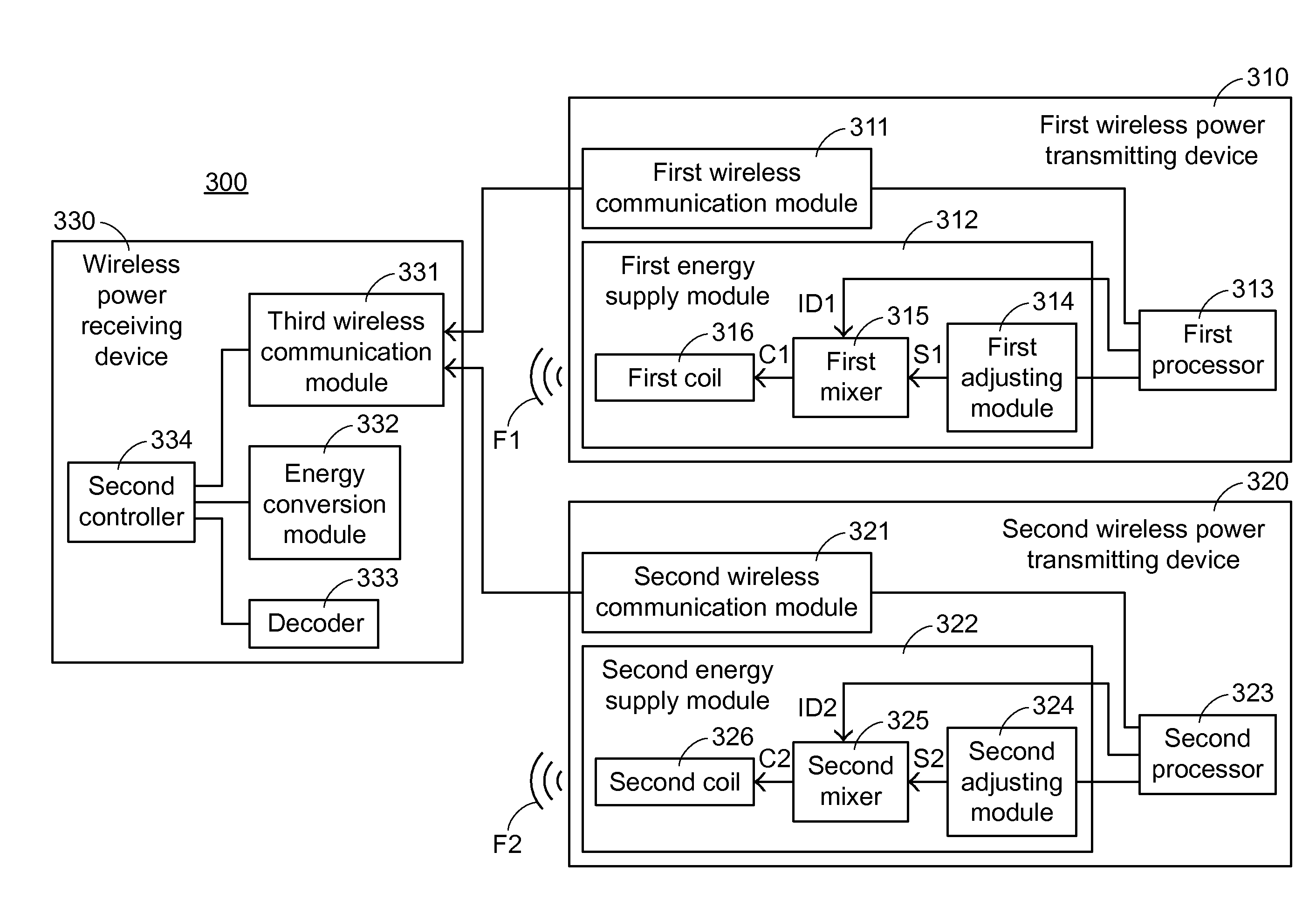
[0086]In the present invention, the wireless power receiving device 330 is located within the effective power transmission range R4 of the second wireless power transmitting device 320, but is not located within the effective power transmission range R3 of the first wireless power transmitting device 310. Consequently, according to the received MAC address and the received identification signal, the wireless power receiving device 330 recognizes the wireless power transmitting device corresponding to the identification signal. Moreover, the wireless power receiving device 330 recognizes the second wireless power transmitting device 320 as the suitable wireless power transmitting device and receives the energy field from the corresponding wireless power transmitting device. Consequently, the wireless charging task of the wireless power receiving device 330 is performed.

second embodiment

[0087]However, if the wireless power receiving device 330 is located within both of the effective power transmission range R3 of the first wireless power transmitting device 310 and the effective communication range R4 of the second wireless power transmitting device 320, the wireless power receiving device 330 of this embodiment still fails to accurately judge whether the suitable wireless power transmitting device is the first wireless power transmitting device 310 or the second wireless power transmitting device 320. For solving this drawback, the present invention further provides a

[0088]FIG. 6 is a schematic functional block diagram illustrating a wireless charging system according to a second embodiment of the present invention. As shown in FIG. 6, the wireless charging system 400 comprises plural wireless power transmitting devices and a wireless power receiving device 430. The plural wireless power transmitting devices of this embodiment comprise a first wireless power trans...


PUM


Abstract

A wireless charging method and a wireless charging system are provided. The wireless charging system includes plural wireless power transmitting devices and a wireless power receiving device. The plural wireless power transmitting devices generate plural energy fields. The energy fields contain plural identification signals, respectively. After the identification signals are decoded, the wireless power receiving device recognizes the plural wireless power transmitting devices corresponding to the plural identification signals. The wireless power receiving device is in wireless connection with the most appropriate wireless power transmitting device to perform the wireless charging task. Consequently, the wireless charging efficiency is enhanced.

Description

FIELD OF THE INVENTION[0001]The present invention relates to a wireless charging method and a wireless charging system, and more particularly to a wireless charging method and a wireless charging system having identification signals in energy fields.BACKGROUND OF THE INVENTION[0002]Nowadays, most electronic devices may be charged by a wired charging technology or a wireless charging technology. In case that the electronic device is charged by the wired charging technology, a charging slot of the electronic device is connected with a connecting terminal of a charger to acquire electric power. In case that the electronic device is charged by the wireless charging technology, the electronic device receives a wireless signal and converts the wireless signal into electric power. Although the wired charging technology is very popular, there are still some drawbacks. For example, after a long use period, the charging slot of the electronic device or the connecting terminal of the charger i...

Claims


Application Information

Patent Timeline
Patent Type & Authority Applications(United States)
IPC IPC(8): H02J7/02H02J5/00H02J7/00
CPCH02J7/025H02J5/005H02J7/007H02J50/80
Inventor HO, YUNG-HSIENCHIU, HUNG-WEILO, CHUN-HAO
Owner PRIMAX ELECTRONICS LTD
Features
  • R&D
  • Intellectual Property
  • Life Sciences
  • Materials
  • Tech Scout
  • Unparalleled Data Quality
  • Higher Quality Content
  • 60% Fewer Hallucinations
Learn More