Indoor unit of an air conditioner

a technology for indoor units and air conditioners, which is applied in the field of indoor units of air conditioners, can solve the problems of high maintenance cost, time and effort for cleaning and maintenance of heat exchangers, and achieve the effect of time and effort for treating piping as required, without taking much time and troubl

Active Publication Date: 2011-03-01
DAIKIN IND LTD
View PDF11 Cites 1 Cited by
  • Summary
  • Abstract
  • Description
  • Claims
  • Application Information

AI Technical Summary

Benefits of technology

It is therefore an object of the present invention to provide an indoor unit of an air conditioner for which maintenance operations can be efficiently performed with less time and effort.
As described above, the indoor unit of the present invention has a heat exchanger, a fan for delivering air to the heat exchanger, a mounting frame on which the heat exchanger and the fan are mounted, the mounting frame having a backside which is to be fixed to a wall; piping connected to the heat exchanger to supply a heat transfer medium to and discharge the heat transfer medium from the heat exchanger, and a pipe retaining member disposed near a lateral side of the mounting frame and near an underside of the mounting frame to retain the piping. Therefore, the pipe retaining member can be easily removed from the mounting frame in a state that the mounting frame is fixed to the wall. Thus, it is not necessary to dismount the whole of the indoor unit from the wall to remove the pipe retaining member as in the conventional air conditioner indoor unit, so that time and effort for treating the piping as required for the conventional indoor unit can be saved. Consequently, the heat exchanger and the mounting frame can be separated from each other without taking time for the piping decoupling, so that maintenance work such as cleaning of the heat exchanger can be performed effectively and efficiently without taking much time and trouble.

Problems solved by technology

However, the conventional indoor unit has a problem that maintenance such as cleaning of the heat exchanger requires much time and effort.
This is why maintenance requires much time and effort.

Method used


Image

  • Indoor unit of an air conditioner
  • Indoor unit of an air conditioner
  • Indoor unit of an air conditioner

Examples


Embodiment Construction

The present invention will be described in detail below according to the embodiments shown in the figures.

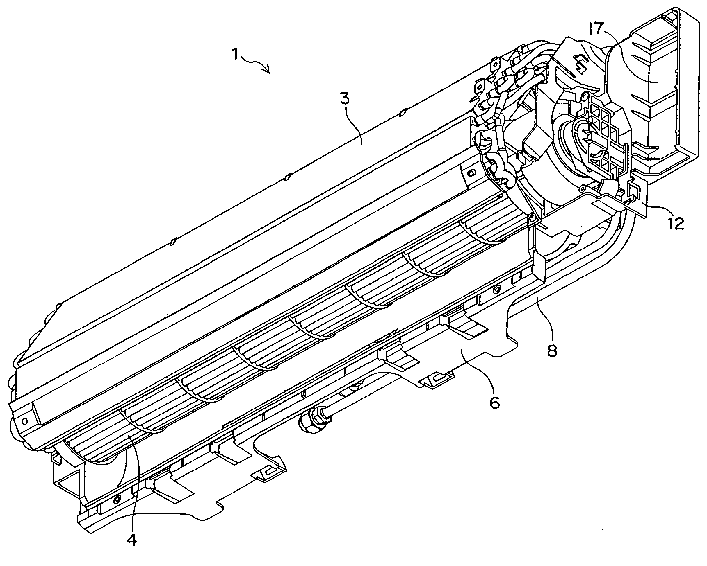
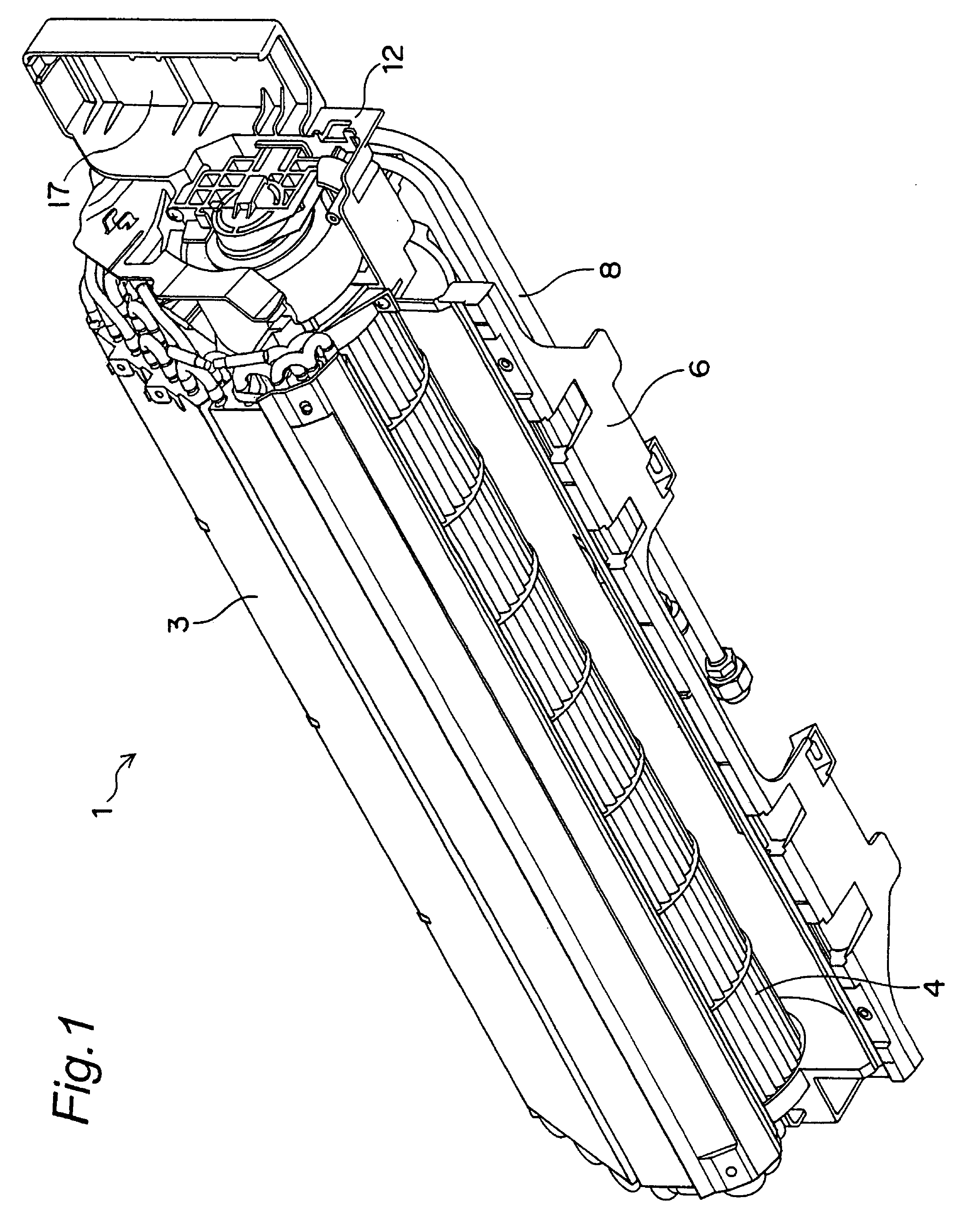
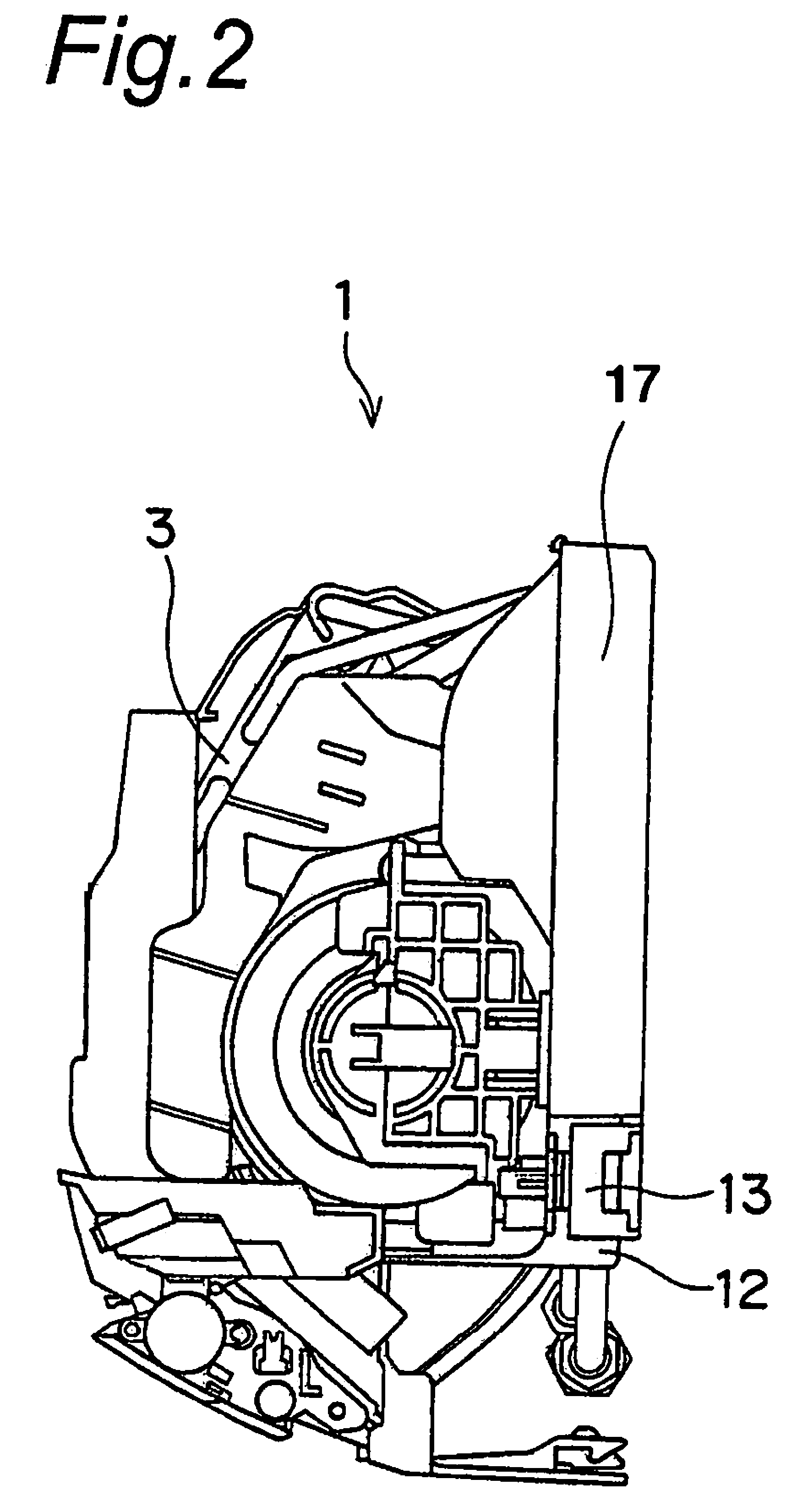
FIG. 1 is a perspective view of an indoor unit of an air conditioner as an embodiment of the present invention viewed from the lower front, FIG. 2 is a side view of the indoor unit, FIG. 3 is a back view of the indoor unit, and FIG. 4 is an enlarged perspective view of a portion near a side of the indoor unit. In FIGS. 1 to 4, parts such as a front cover for covering the front face of the indoor unit are not shown.

The air conditioner indoor unit 1 has a heat exchanger 3 for performing heat exchange between refrigerant as a heat transfer medium and room air, and a mounting frame 6 on which the heat exchanger 3 is mounted. In addition to the heat exchanger 3, a fan 4 for delivering the room air to the heat exchanger 3, a motor for driving the fan 4, a flap for changing the direction of air flow caused by the fan 4, a motor for driving the flap, etc. are mounted on the mounting fra...


PUM


Abstract

An indoor unit of an air conditioner wherein a pipe retaining member retaining auxiliary piping connected to a heat exchanger is disposed near both a lateral side and an underside of a mounting frame. The pipe retaining member is bent in an L-shape, and its short plate is exposed on the underside of the mounting frame. The pipe retaining member can be removed only by slightly separating a lower part of the mounting frame from a wall in the fixed state of the indoor unit to the wall. Since the heat exchanger can be separated from the mounting frame without disconnecting the auxiliary piping from communication piping, maintenance work such as washing of the heat exchanger is efficiently performed without requiring much time and effort for separating the auxiliary piping from the communication piping.

Description

CROSS-REFERENCE TO RELATED APPLICATIONSThis U.S. National stage application claims priority under 35 U.S.C. §119(a) to Japanese Patent Application No. 2004-265407, filed in Japan on Sep. 13, 2004, the entire contents of which are hereby incorporated herein by reference.BACKGROUND OF THE INVENTIONThe present invention relates to an indoor unit of an air conditioner, and in particular to a wall mounted type indoor unit of an air conditioner, which unit is mounted on a wall in a room.Conventionally, this type of indoor unit of an air conditioner has a heat exchanger, a fan for leading room air to the heat exchanger, and a mounting frame on which the heat exchanger and the fan are mounted, wherein the back of the mounting frame is fixed to a wall surface in a room (see JP 5-47721 U, for example).The heat exchanger is connected with auxiliary piping for supplying refrigerant to and discharging it from the heat exchanger. The auxiliary piping is led from the frontside of the mounting fram...

Claims


Application Information

Patent Timeline
Patent Type & Authority Patents(United States)
IPC IPC(8): F25D19/00F25D23/12F25D17/06F24F1/0063F24F1/0057
CPCF24F1/0007F24F1/26F24F1/32F24F13/32F24F2001/0048F24F1/0057F24F1/0063F24F1/00F24F13/00
Inventor INOUE, KIYOSHIWAKIHARA, KATSUHIROYAMADA, TOSHIAKIYAMADA, IKUHIROKASHIWA, SHIRO
Owner DAIKIN IND LTD
Why Eureka
Try Eureka