Leak detection system and leak detection method

a leak detection system and leak detection technology, applied in the direction of fluid tightness measurement, instruments, investigating moving fluids/granular solids, etc., can solve the problems of reducing and further damaging the functionality of the motor assembly and the vehicle, reducing the cooling efficiency, and destroying the inverter, the motor and the gearbox, so as to achieve effective and efficient leak detection process

Inactive Publication Date: 2019-02-28
SHANGHAI XPT TECH LTD
View PDF0 Cites 2 Cited by
  • Summary
  • Abstract
  • Description
  • Claims
  • Application Information

AI Technical Summary

Benefits of technology

[0003]The present invention provides a leak detection system and a leak detection method for effectively and efficiently performing the leak detection process to the motor car assembly.

Problems solved by technology

However, if the inverter, the motor and the gearbox are not properly sealed and causing cooling medium leaks, cooling efficiency may reduce and further damaging functionality of the motor assembly and the vehicle.
The prior art uses fluorescent agent while performing the leak detection process, which may damage the inverter, the motor and the gearbox.
Therefore, the conventional leak detection system and method may not effectively and efficiently perform the leak detection process to the car motor assembly.

Method used


Image

  • Leak detection system and leak detection method
  • Leak detection system and leak detection method
  • Leak detection system and leak detection method

Examples


Embodiment Construction

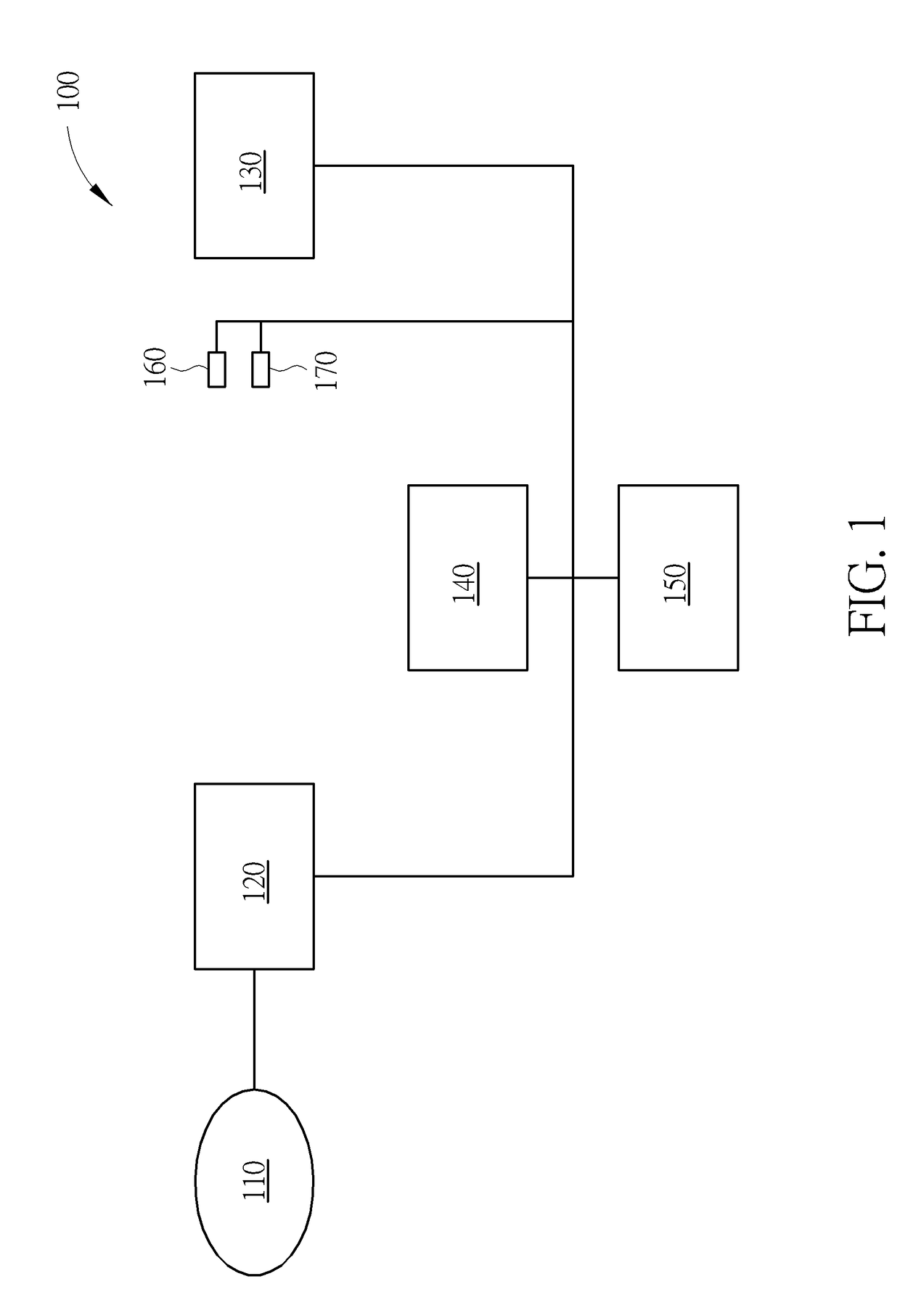
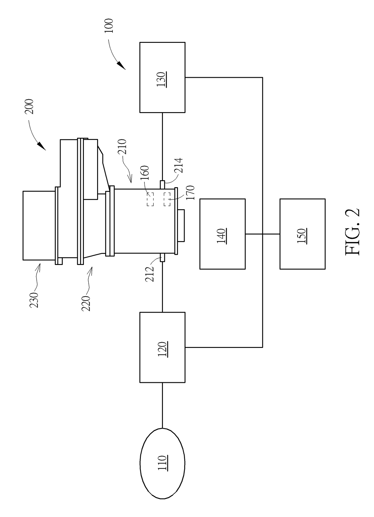
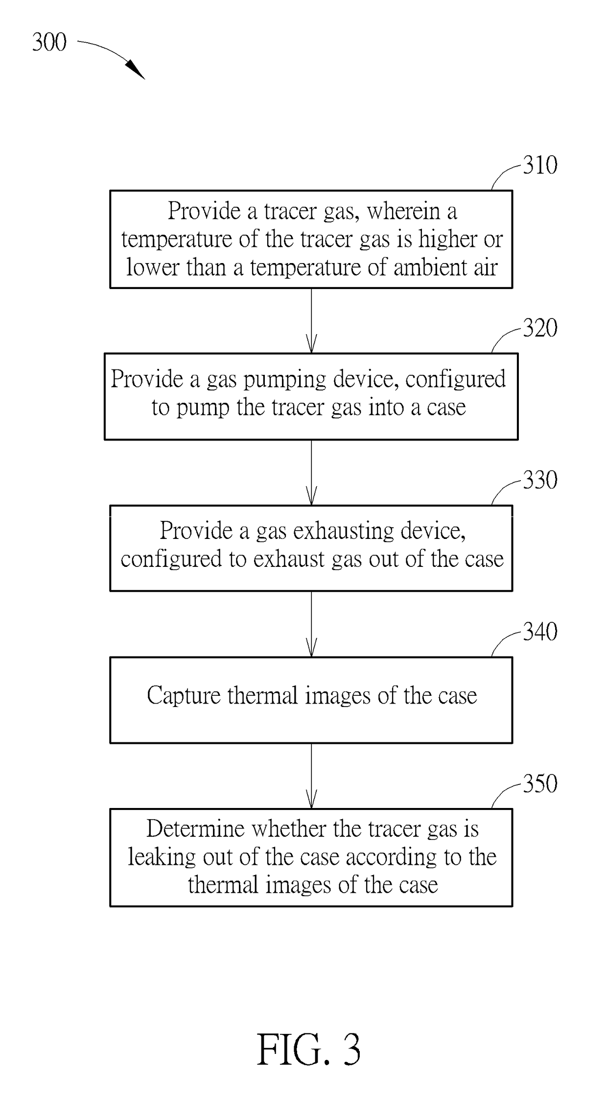
[0010]FIG. 1 is a schematic diagram of a leak detection system according to one embodiment of the present invention. As shown, the leak detection system 100 of the present invention may include a gas supplying device 110, a gas pumping device 120, a gas exhausting device 130, a thermal image capturing device 140 and a processing unit 150. The gas supplying device 110 provides a tracer gas, wherein a temperature of the tracer gas is higher or lower than a temperature of ambient air. For example, the tracer gas can be atmospheric air, easily obtained gas or non-corrosive gas (e.g. nitrogen or carbon dioxide). A temperature of the tracer gas may be a preset value higher or lower (e.g. 100° C.) than room temperature (e.g. 25° C.), and the present invention is not limited herein. A temperature difference between the tracer gas and ambient air may be varied based on specific detection scenarios. The gas pumping device 120 is connected to the gas supplying device 110, configured to pump th...


PUM

PropertyMeasurementUnit
temperatureaaaaaaaaaa
thermal image capturingaaaaaaaaaa

Abstract

A leak detection system, comprising a gas supplying device, configured to provide a tracer gas, wherein a temperature of the tracer gas is higher or lower than a temperature of ambient air; a gas pumping device, connected to the gas supplying device, configured to pump the tracer gas into a case; a gas exhausting device, configured to exhaust gas out of the case; a thermal image capturing device, configured to capture thermal images of the case; and a processing unit, electrically connected to the thermal image capturing device, configured to determine whether the tracer gas is leaking out of the case according to the thermal images of the case.

Description

BACKGROUND OF THE INVENTION1. Field of the Invention[0001]The present invention relates to a leak detection system and a leak detection method thereof, and more particularly, to a leak detection system and a leak detection method utilizing high temperature or low temperature gas for the leak detection process.2. Description of the Prior Art[0002]A conventional car motor assembly includes an inverter, a motor and a gearbox. The inverter transforms DC voltage from a battery to AC voltage, for driving the motor. The gearbox delivers power generated by the motor to other connected components for propelling the vehicle. The inverter, the motor and the gearbox are jointly connected inside an enclosed case. When the car motor assembly is running, the inverter, the motor and the gearbox generate heat. In order to maintain functionality and efficiency of the car motor assembly from degradation from heat, the conventional art utilizes cooling medium flowing through the car motor assembly to d...

Claims


Application Information

Patent Timeline
Patent Type & Authority Applications(United States)
IPC IPC(8): G01M3/00G06T7/20G01N21/85
CPCG01M3/002G06T7/20G01N21/85G01N2021/8578
Inventor HUANG, MU-JENTAI, YA-LICHEN, TIANLE
Owner SHANGHAI XPT TECH LTD
Why Eureka
Try Eureka