Pneumatic tire

a technology of pneumatic tires and slits, which is applied in the direction of vehicle components, transportation and packaging, non-skid devices, etc., can solve the problems of insufficient drainage performance at slits, and achieve the effects of short tire braking distance, reduced probability of occurrence of deflective wear of tread 1, and reduced tire braking distan

Active Publication Date: 2016-04-14
TOYO TIRE & RUBBER CO LTD
View PDF7 Cites 15 Cited by
  • Summary
  • Abstract
  • Description
  • Claims
  • Application Information

AI Technical Summary

Benefits of technology

[0035]Advantageous effects of the pneumatic tire having the structure as described above will be described.
[0036]As described above, the first tapered portion 21 and the second tapered portion 25 are formed on two of the side walls 23 and 27 of the slits 2, and a plurality of the slits 2 are arranged in the tire circumferential direction. Therefore, the land portion interposed between the two slits 2 and 2 is provided with tapered portions at both ends on a stepping-on side and a kicking side. Therefore, a contact pressure applied to the portion in the vicinity of the ends of the land portions is reduced, so that the contact pressure is relatively even in the land portion. Therefore, the braking distance of the tire is reduced, and probability of occurrence of deflective wearing of the tread 1 is reduced.
[0037]Water flowing along the main groove 11 hits against the side wall 27 on the side of the land portion 16 which comes into contact with the ground later when the tire is rotating (that is, the land portion located in the tire rotational direction with respect to the slit 2) at a portion in the vicinity of the opening end of the slit 2 opening into the main groove 11, and enters the slit 2. A flow channel of the water is as indicated by an arrow in FIG. 2A. The water that has entered the slits 2 passes in the slit 2 and is discharged to the outside in the tire width direction.
[0038]In this embodiment, the end 26 of the second tapered portion 25 on the main groove 11 side is apart from the main groove 11 in comparison with the end 22 of the first tapered portion 21 on the...

Problems solved by technology

However, there is a problem of insufficient drainage performance at slits, which...

Method used


Image

  • Pneumatic tire
  • Pneumatic tire
  • Pneumatic tire

Examples


Embodiment Construction

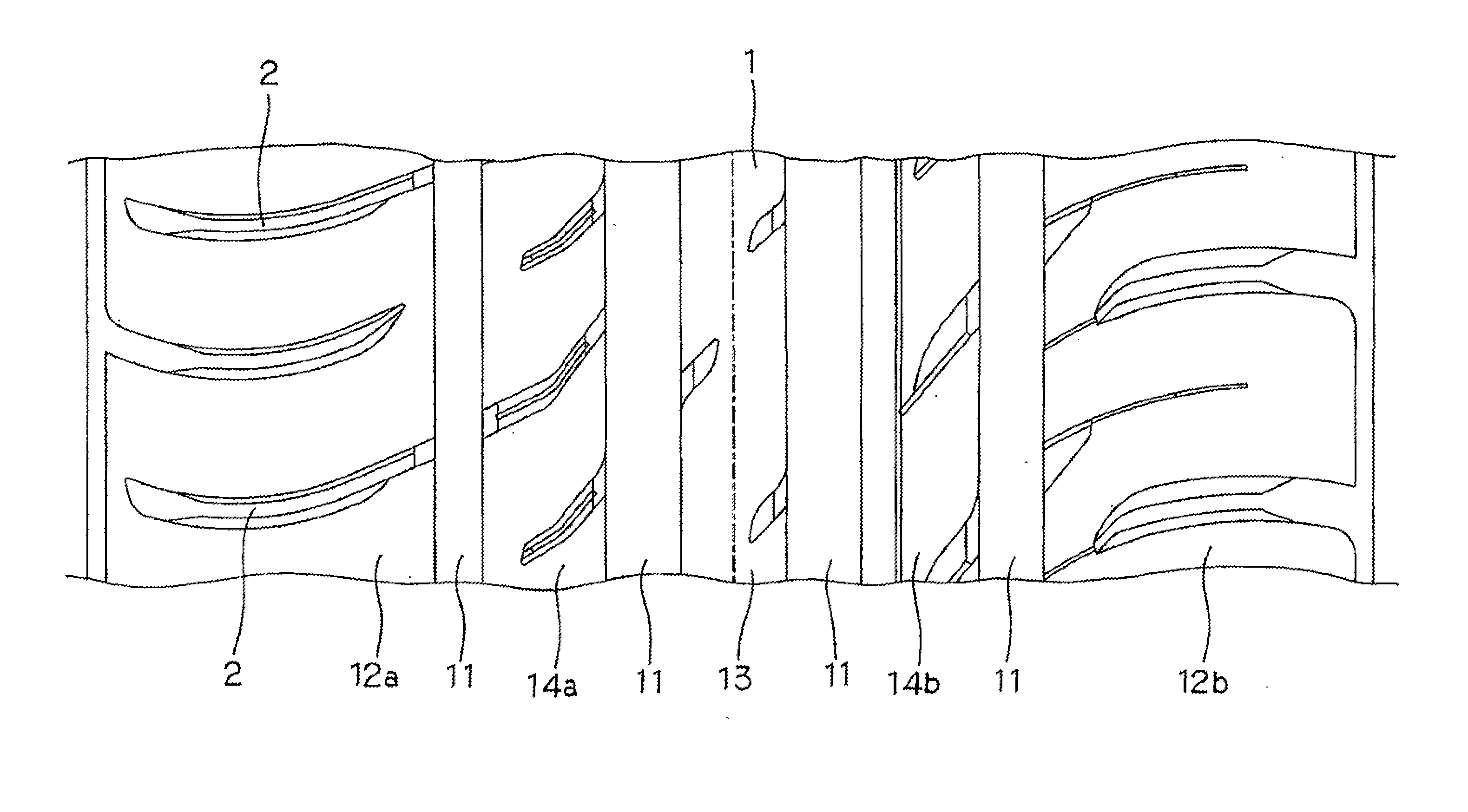
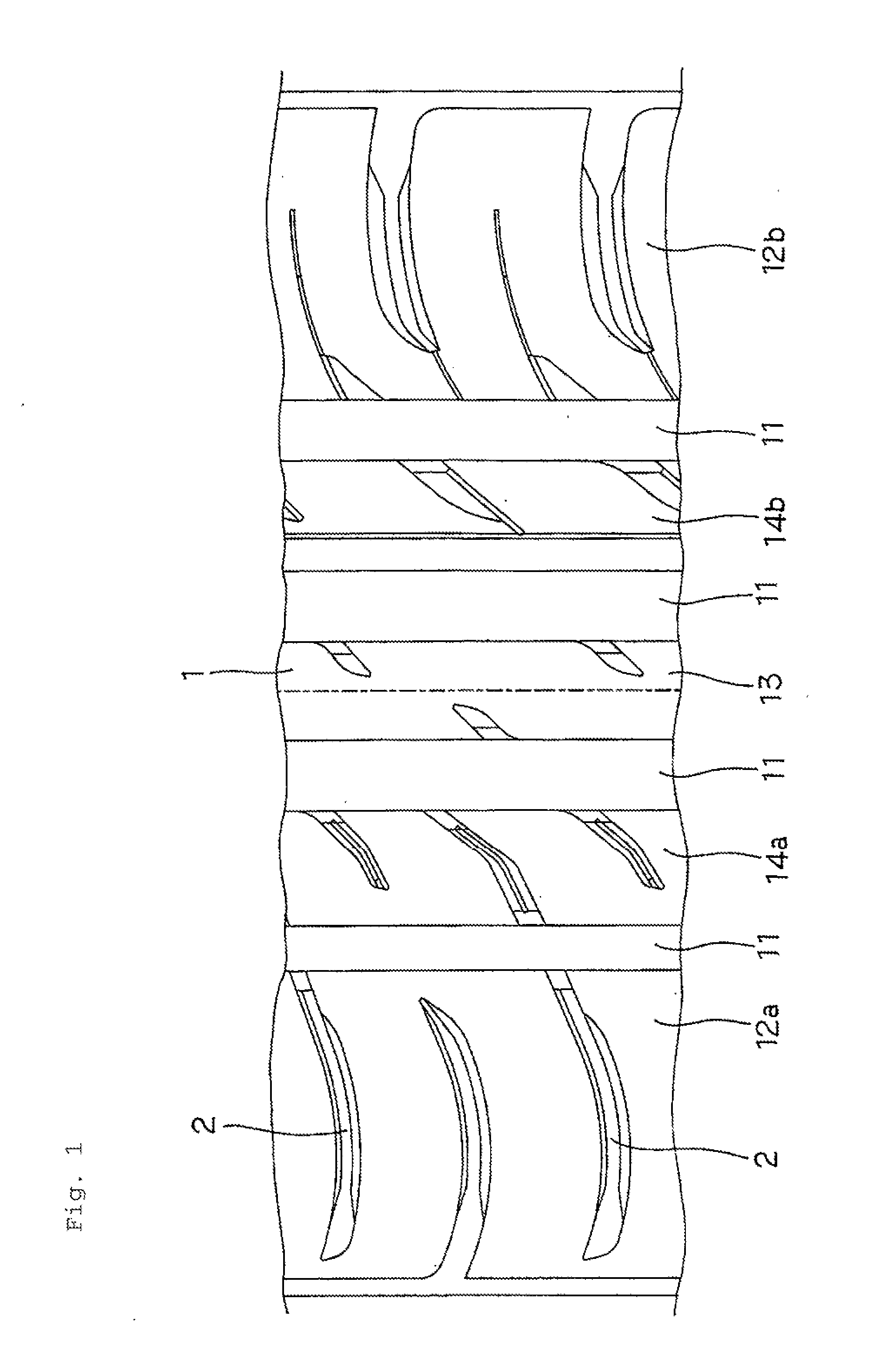
[0020]A cross-sectional structure of a pneumatic tire of an embodiment is a known structure. Specifically, a belt layer or the like is provided on a carcass which forms a mainframe of the tire, and a tread 1 is provided thereon. The tread 1 is provided with a tread pattern as illustrated in FIG. 1 on a surface thereof.

[0021]In the embodiment in FIG. 1, four main grooves 11 extending in a tire circumferential direction are provided in the tread 1. The tread 1 is also provided with shoulder portions 12a and 12b on both sides in a tire width direction, a center portion 13 at a center in the tire width direction, and mediate portion 14a and 14b between the center portion 13 and the shoulder portions 12a and 12b by being isolated by the main grooves 11.

[0022]At least one of the shoulder portions 12a and 12b is provided with groove-shaped slits 2 described later. In this embodiment, the shoulder portion 12a which is on the OUT side (outside in a vehicle width direction) when being mounted...


PUM


Abstract

A pneumatic tire is provided with a tread having a shoulder portion isolated by a main groove, and a slit formed on the shoulder portion, wherein a first tapered portion is formed on a side wall of the slit which comes into contact with the ground first when the tire is rotating, and a second tapered portion is formed on the side wall of the slit which comes into contact with the ground later, an end of the first tapered portion on the main groove side is located at a position closer to the main groove than the end of the second tapered portion on the main groove side, and the second tapered portion is formed so that a width on an opening end of the slit opening at a contact surface is wider than the width of the portion where the second tapered portion is not formed.

Description

REFERENCE OF RELATED APPLICATION[0001]This application enjoys priority benefit from this application on the basis of Japanese Patent Application No. 2014-208164 (applied Oct. 9, 2014).BACKGROUND OF THE INVENTION[0002]1. Field of the Invention[0003]The present invention relates to a pneumatic tire.[0004]2. Background Art[0005]Generally, a tread of a pneumatic tire includes wide main grooves extending in a tire circumferential direction, and relatively narrow slits extending in a tire width direction. In addition, a plurality of land portions segmented by the main grooves and the slits are formed. The pneumatic tire as described above is subjected to a large contact pressure applied in the vicinity of ends of the land portions on braking, so that the contact pressure is uneven in the land portion. Consequently, a braking distance may be increased or deflective wear may be generated.[0006]In contrast, as described in JP-A-2007-112218 and JP-A-2009-61985, there is a pneumatic tire where...

Claims


Application Information

Patent Timeline
IPC IPC(8): B60C11/03B60C11/13
CPCB60C11/0327B60C2011/1361B60C11/1353B60C11/1392B60C11/0304B60C2011/0369B60C11/1323B60C2011/0395
Inventor SHIBAYAMA, KENSUKE
Owner TOYO TIRE & RUBBER CO LTD
Why Eureka
Try Eureka