Collision detection system and method of operation

a collision detection and detection system technology, applied in the field of vehicle radar, can solve the problems that speed detection radar alone cannot generate an alarm to alert an officer to the potential danger, and travel at a lawful speed might still collide with a parked patrol car

Active Publication Date: 2016-04-14
APPLIED CONCEPTS
View PDF5 Cites 51 Cited by
  • Summary
  • Abstract
  • Description
  • Claims
  • Application Information

AI Technical Summary

Problems solved by technology

However, a vehicle that is traveling at a lawful speed might still collide with a parked patrol car, due to driver incapacity.
In such cases, the speed detection radar alone cannot generate an alarm to alert an officer to the potential danger.

Method used


Image

  • Collision detection system and method of operation
  • Collision detection system and method of operation
  • Collision detection system and method of operation

Examples


Embodiment Construction

[0012]In the description that follows, like parts are marked throughout the specification and drawings with the same reference numerals. The drawing figures might not be to scale and certain components can be shown in generalized or schematic form and identified by commercial designations in the interest of clarity and conciseness.

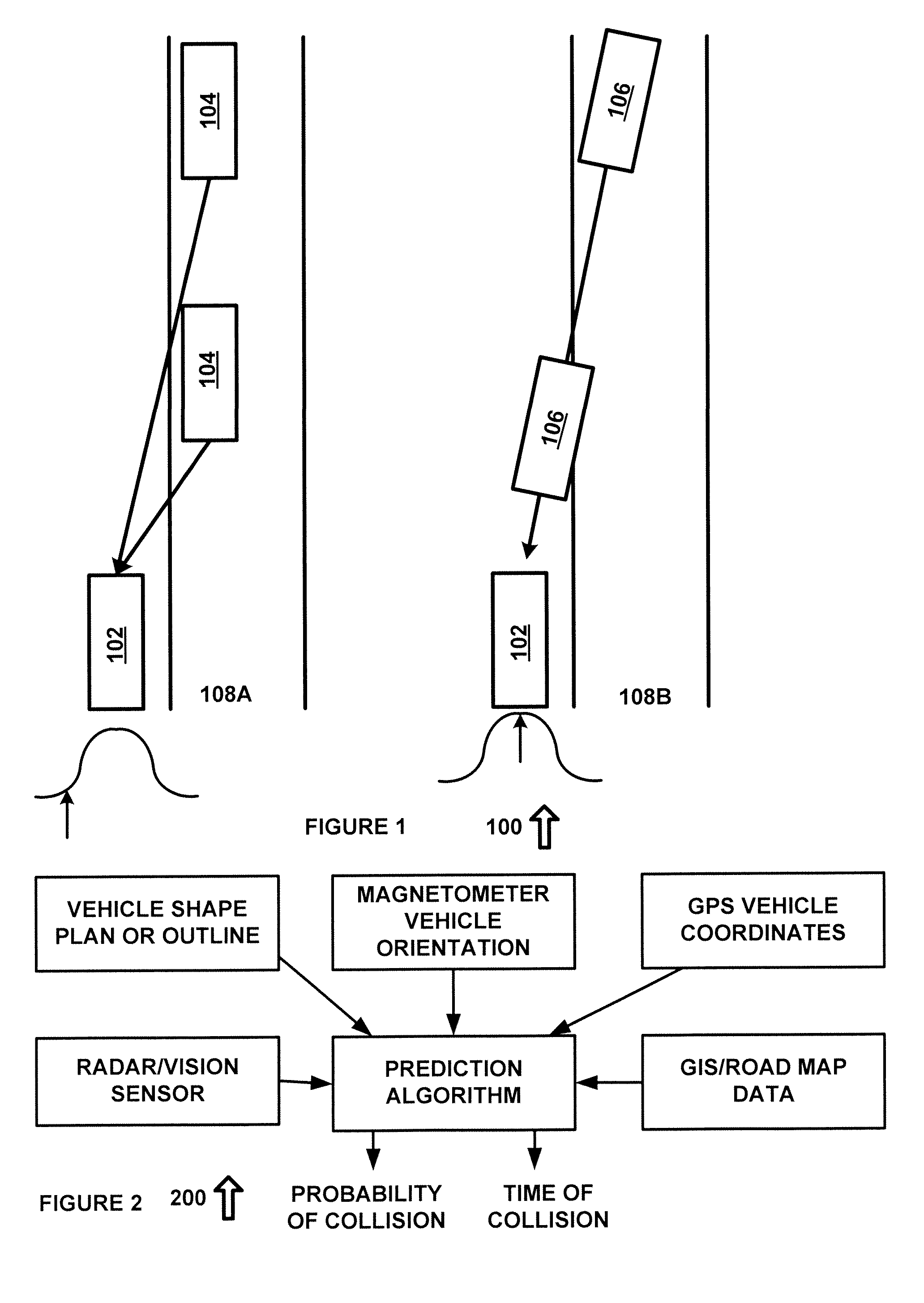
[0013]FIG. 1 is a diagram of a system 100 in accordance with an exemplary embodiment of the present disclosure. System 100 includes patrol car 102, which includes a collision detection system that can determine the trajectory, speed and range of an oncoming vehicle. Road 108A shows a vehicle 104 at two locations. At the first location, vehicle 104 has an angle relative to patrol car 102 that is different from the angle of vehicle 104 at the second location. The changing angle here is indicative that vehicle 104 is not heading in the direction of patrol car 102, which is parked on the side of road 108A. The possibility of a collision can be associated with ...


PUM


Abstract

A system for detecting driver vehicle travelling in an unsafe manner comprising a radar system configured to generate a sequence of frames of radar data. A target trajectory system configured to receive the sequence of frames of radar data and to generate target trajectory data for a vehicle. An alarm system configured to receive the target trajectory data and to generate an alarm as a function of the target trajectory data, a probability of collision, a degree of erratic driving or other suitable data.

Description

TECHNICAL FIELD[0001]The present disclosure relates generally to vehicular radar, and more specifically to a vehicular radar system for collision detection and an associated method of operation.BACKGROUND OF THE INVENTION[0002]Speed detection radar can identify vehicles using reflected radar signals and can associate each vehicle with a corresponding speed. However, a vehicle that is traveling at a lawful speed might still collide with a parked patrol car, due to driver incapacity. In such cases, the speed detection radar alone cannot generate an alarm to alert an officer to the potential danger.SUMMARY OF THE INVENTION[0003]A system for detecting a vehicle travelling in an unsafe manner is provided that includes a radar system configured to generate a sequence of frames of radar data. A target trajectory system receives the sequence of frames of radar data and generates target trajectory data for a vehicle. An alarm system receives the target trajectory data and generates an alarm ...

Claims


Application Information

Patent Timeline
Patent Type & Authority Applications(United States)
IPC IPC(8): G01S13/93B60Q9/00B60Q5/00G01S13/931
CPCG01S13/931B60Q9/008B60Q5/00G01S13/723G01S13/86G01S2013/93272G01S2013/93271B60Q5/006
Inventor MANDAVA, MAHENDRAGAMMENTHALER, ROBERT S.
Owner APPLIED CONCEPTS
Why Eureka
Try Eureka