Method and Device for Operating a Braking Device, Braking Device

Active Publication Date: 2016-04-14
ROBERT BOSCH GMBH
View PDF3 Cites 9 Cited by
  • Summary
  • Abstract
  • Description
  • Claims
  • Application Information

AI Technical Summary

Benefits of technology

The method in this patent allows for the determination of motor parameters during braking, taking into account external conditions like temperature. The actuator element is displaced, and the motor input voltage and current are measured. These measurements are used to calculate the motor parameters, which are then used to calculate the brake application force and the travel distance of the actuator element during brake release. This helps to improve the accuracy and efficiency of the braking process.

Problems solved by technology

However, for reasons of cost, the force is not measured directly.
Moreover, the distance travelled must not be too large, which—without a further calibrating measure—could result in an increased closing time period during the next subsequent brake application procedure.

Method used


Image

  • Method and Device for Operating a Braking Device, Braking Device
  • Method and Device for Operating a Braking Device, Braking Device
  • Method and Device for Operating a Braking Device, Braking Device

Examples


Embodiment Construction

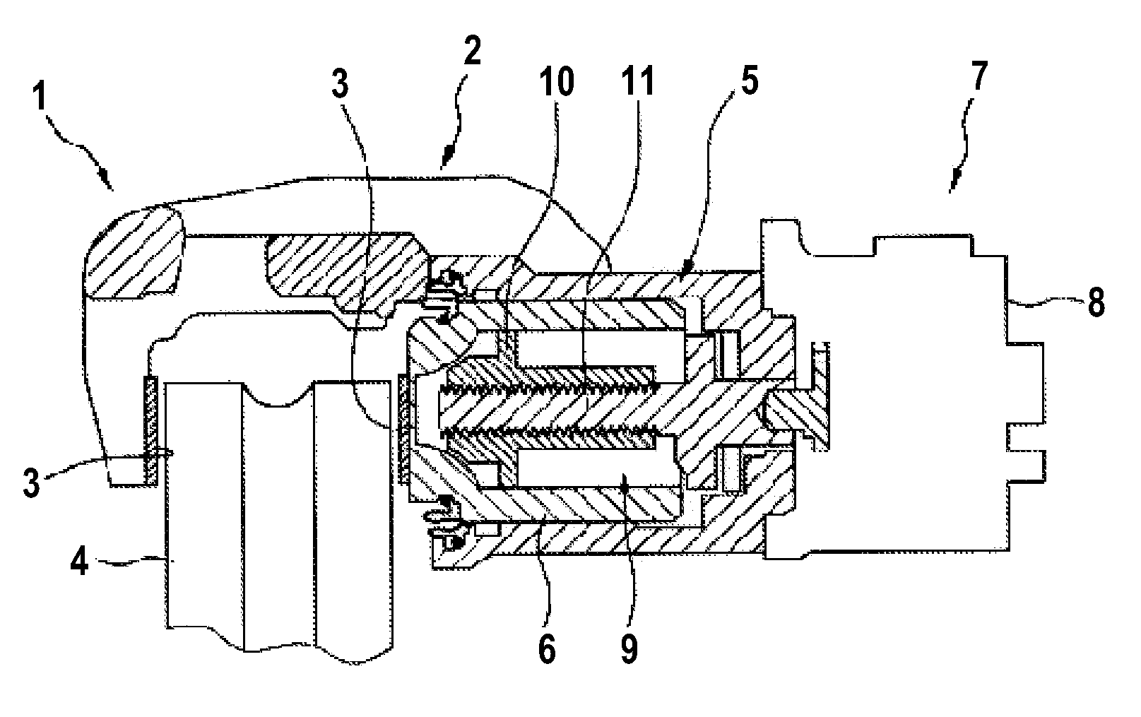
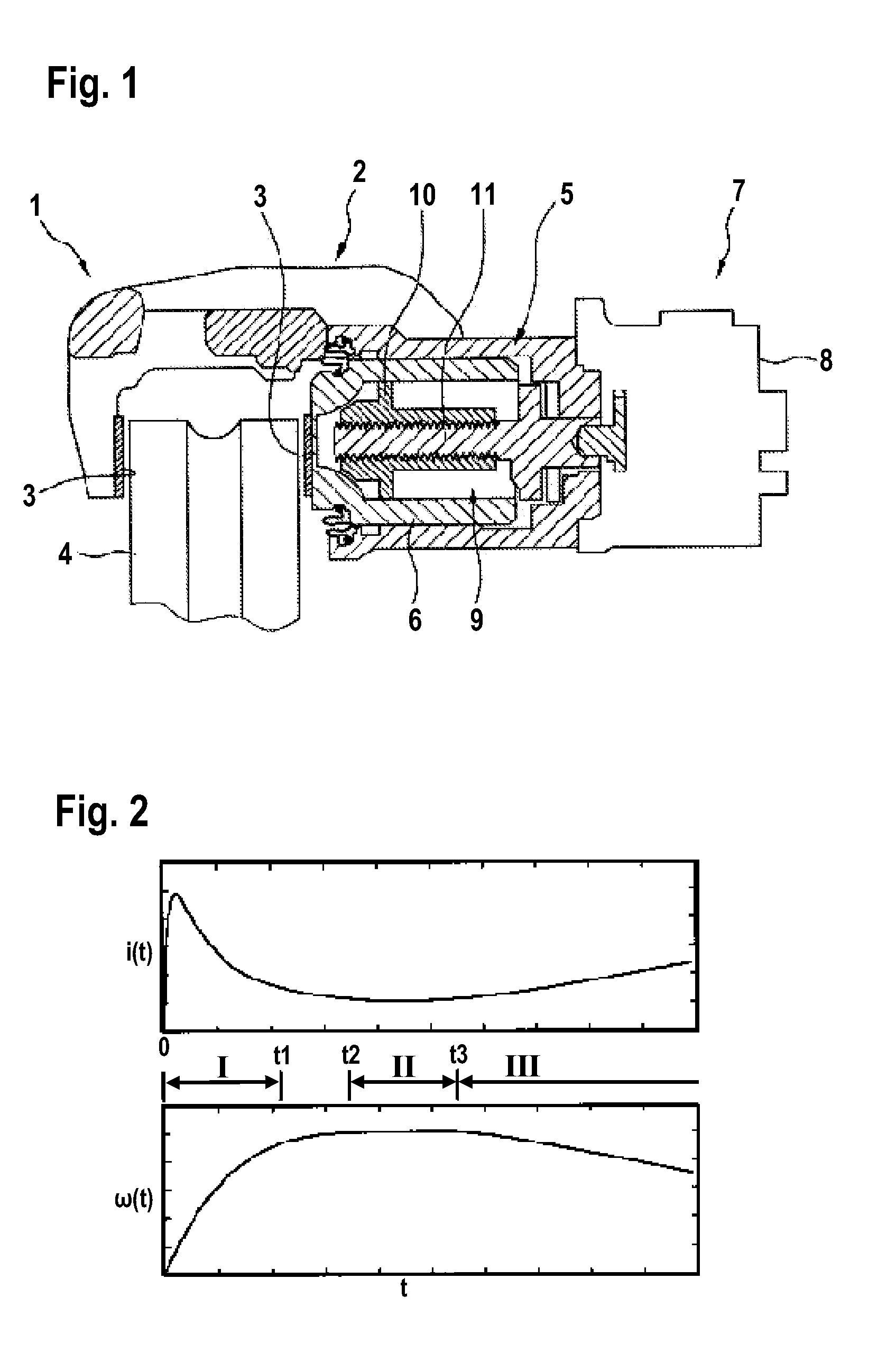
[0022]FIG. 1 illustrates in a simplified cross-sectional view a braking device 1 of a motor vehicle not illustrated in the figure in detail. The braking device 1 is embodied as a disc brake and comprises for this purpose a brake caliper 2 that supports the brake linings 3 and between which it is possible to jam or clamp a brake disc 4 that is connected in a non-rotatable manner to a wheel of the motor vehicle. For this purpose, a hydraulic actuator 5 is allocated to the brake caliper 2 and said hydraulic actuator comprises a brake piston 6 that can be actuated in a hydraulic manner in order to clamp the brake disc 4 as required between the brake linings 3. As a consequence, a braking torque is applied during the driving operation to the brake disc 4 and thus to the wheels and said braking torque is used for the purpose of decelerating the vehicle.

[0023]Furthermore, the braking device 1 is embodied as a parking brake device or rather has a parking brake function and comprises for thi...


PUM


Abstract

The disclosure relates to a method for operating a braking device, in particular a parking brake device, which comprises an actuator having an electric motor that displaces an actuator element as desired into a brake application position or into a brake release position, wherein the electric motor is controlled in dependence upon a motor constant and an electrical resistance of the electric motor, characterized in that as the actuator element is displaced a prevailing motor input voltage and a prevailing motor current are ascertained, and that the motor constant and the electrical resistance are determined in dependence upon the ascertained motor input voltage and the ascertained motor current.

Description

[0001]This application claims priority under 35 U.S.C. §119 to application no. DE 10 2014 220 793.2, filed on Oct. 14, 2014 in Germany, the disclosure of which is incorporated herein by reference in its entirety.BACKGROUND[0002]The disclosure relates to a method for operating a braking device, in particular a parking brake device, which comprises an actuator having an electric motor that displaces an actuator element as desired into a brake application position or into a brake release position, wherein the electric motor is controlled in dependence upon a motor constant and an electrical resistance of the electric motor.[0003]Moreover, the disclosure relates to a device for operating a braking device of this type having the features of the disclosure and a braking device having the features of the disclosure.[0004]Methods and apparatuses and also braking devices of the type mentioned in the introduction are known from the prior art. Braking devices having an electrically motorized a...

Claims


Application Information

Patent Timeline
IPC IPC(8): G05B11/01G05G5/00F16D71/00F16D65/18H02P3/00
CPCG05B11/01F16D65/18F16D2121/24F16D71/00G05G5/00H02P3/00B60T13/746H02P7/00H02P23/14F16D55/226
Inventor BAEHRLE-MILLER, FRANKSUSSEK, ULLRICHFLEISCHER, SIMONBLESSING, PETER
Owner ROBERT BOSCH GMBH
Why Eureka
Try Eureka