Sonar Based Drowning Detection System, Method And Kit

a detection system and sonar technology, applied in the field of drowning monitoring, can solve the problems of long-term disability, permanent loss of basic functioning, memory problems, etc., and achieve the effect of avoiding interferen

Active Publication Date: 2016-04-14
KHALIFA UNIV OF SCI & TECH
View PDF0 Cites 23 Cited by
  • Summary
  • Abstract
  • Description
  • Claims
  • Application Information

AI Technical Summary

Benefits of technology

[0031]In an embodiment of the invention, the sonar sensors have different frequency / phase operation ranges for avoiding any interference between them.

Problems solved by technology

These nonfatal drowning injuries can cause severe brain damage that may result in long-term disabilities such as memory problems, learning disabilities, and permanent loss of basic functioning (e.g., permanent vegetative state).
The main factors that affect drowning risk are lack of swimming ability, lack of barriers to prevent unsupervised water access, lack of close supervision while swimming, location, and failure to wear life jackets, alcohol use, and seizure disorders.
These systems detect objects that enter the pool but do not differentiate between swimming people and drowning people.
However it does not incorporate a detection system.
Glare can be a potential problem with viewing monitors in bright environments for CCTV based systems.
There are also cultural and religious issues with respect to the use of cameras in swimming pools in some countries which limit substantially their use in a big number of countries.
Such a wristband has some drawbacks in terms of reliability some of which are as follows: It cannot be used in salt or sea water.
This is a serious limitation since many new pools and water parks are being made with salt water.
This means that this wristband will not reliably work in all water environments or even at the seaside.
It requires line of sight between the receiver and the transmitter, so it may not work if there is an obstacle between the base-station and the child.

Method used


Image

  • Sonar Based Drowning Detection System, Method And Kit
  • Sonar Based Drowning Detection System, Method And Kit
  • Sonar Based Drowning Detection System, Method And Kit

Examples


Embodiment Construction

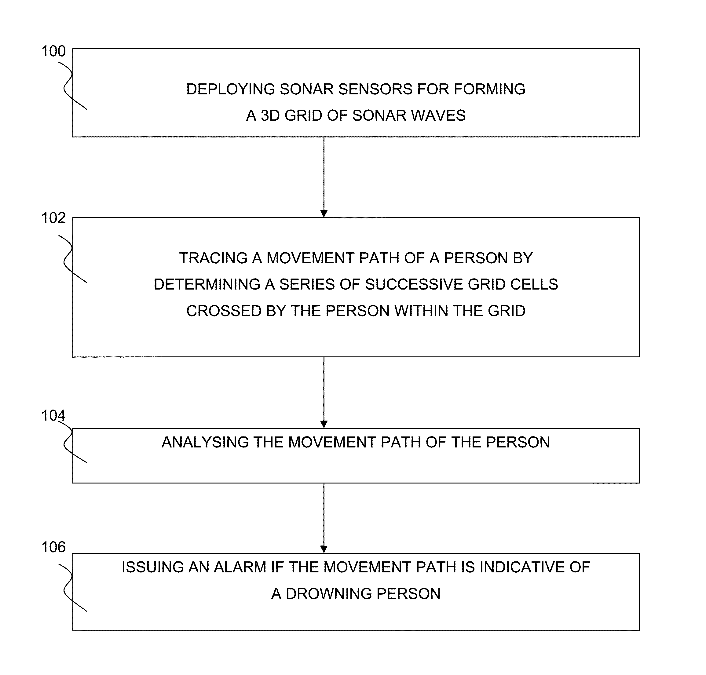
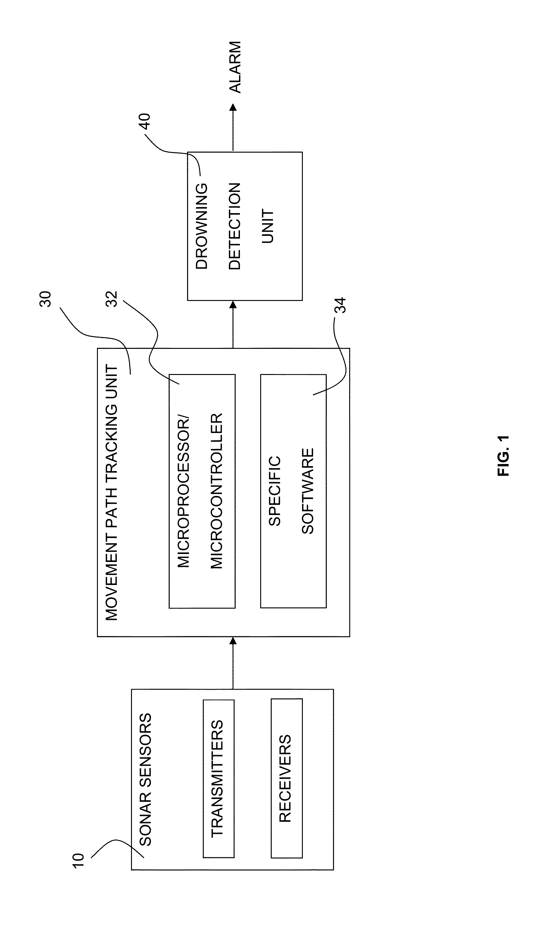
[0049]As illustrated in FIGS. 1 and 3, there is provided sonar based drowning monitoring system 2. The system 2 comprises sonar sensors 10, a movement path tracing unit 30 and a drowning detection unit 40. The movement path tracing unit 30 and the drowning detection unit 40 can be constitute a same physical unit and / or be part of a same computer system 50.

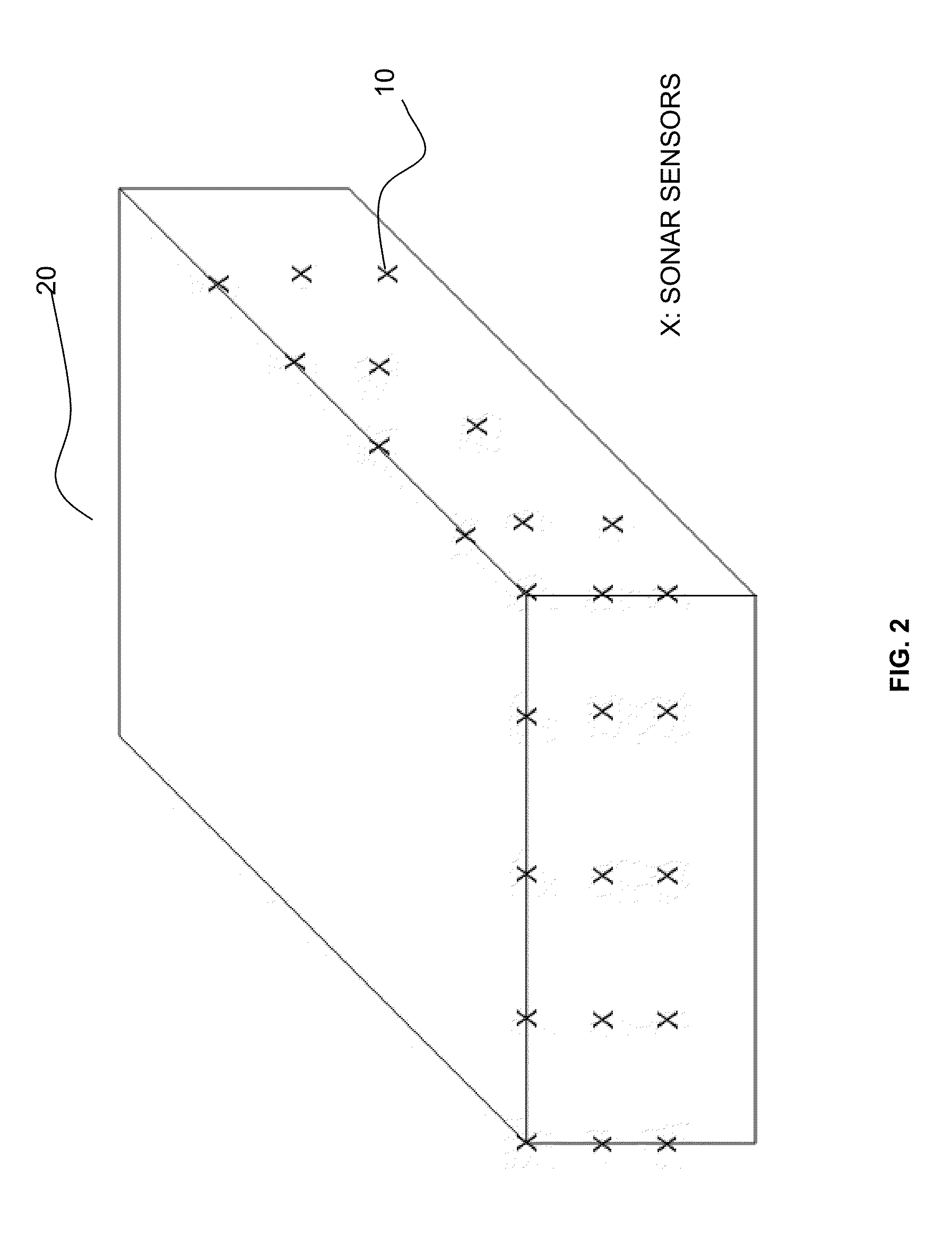
[0050]The sonar sensors 10 are adapted to be deployed in a certain geometrical configuration according to the shape of the water body 20 where it is to be deployed. The sonar sensors 10 comprise sonar transmitters 14 and sonar receivers 16 for respectively transmitting and receiving sonar waves in a predefined frequency / phase range. The sonar transmitters 14 and receivers 16 can be located in the same place (monostatic operation) or separated (bistatic operation).

[0051]The sonar sensors 10 are deployed in such a manner to transmit and receive directed sonar waves without dispersing or overlapping. As illustrated in FIG. 4, the sona...


PUM


Abstract

There is provided a system for detecting a drowning person within a water body, the system comprising (i) sonar sensors for forming a three dimensional grid of sonar waves within the water body, the grid having three dimensional grid cells; (ii) a movement path tracing unit adapted to be connected to the sonar sensors for tracing a movement path of a person within the water body by determining a sequence of successive grid cells crossed by the person within the grid in the course of said movement path, the determination of the successive grid cells being made based on detected propagation delays of the sonar waves forming the grid; and (iii) a drowning detection unit adapted to be connected to the movement path tracing unit for analysing the movement path of the person and issuing an alarm when the movement path of the person is indicative of a drowning person movement path. There is also provided a kit and method for detecting a drowning person within a water body.

Description

FIELD OF THE INVENTION[0001]The present invention relates generally to the field of drowning monitoring, and more specifically to a system for sonar based drowning detection system, kit and method.BACKGROUND OF THE INVENTION[0002]Every day, about ten people die from unintentional drowning. Of these, two are children aged 14 or younger. Drowning ranks fifth among the leading causes of unintentional injury death in the United States.[0003]From 2005-2009, there were an average of 3,533 fatal unintentional drowning (non-boating related) annually in the United States—about ten deaths per day. An additional 347 people died each year from drowning in boating-related incidents. About one in five people who die from drowning are children 14 and younger. For every child who dies from drowning, another five receive emergency department care for nonfatal submersion injuries. More than 50% of drowning victims treated in emergency departments (EDs) require hospitalization or transfer for further ...

Claims


Application Information

Patent Timeline
Patent Type & Authority Applications(United States)
IPC IPC(8): G08B21/08G01S15/66
CPCG01S15/66G08B21/08G01S7/539G01S15/42G01S15/88G08B21/084
Inventor ALMAHMOUD, ABDELRAHMAN ALI
Owner KHALIFA UNIV OF SCI & TECH
Why Eureka
Try Eureka