Offsite irrigation controller

a controller and offsite technology, applied in watering devices, horticulture, agriculture, etc., can solve the problems of system cost, and achieve the effects of reducing cost, facilitating installation, and minimizing complexity

Active Publication Date: 2016-04-21
LENNARD TECH LLC
View PDF0 Cites 7 Cited by
  • Summary
  • Abstract
  • Description
  • Claims
  • Application Information

AI Technical Summary

Benefits of technology

The present invention has the following technical effects: it is easy to install and requires minimal skills, and it is a much more affordable and simple than other irrigation system controllers.

Problems solved by technology

These systems are usually costly and generally are installed by a technician, as opposed to the farmer.

Method used


Image

  • Offsite irrigation controller
  • Offsite irrigation controller
  • Offsite irrigation controller

Examples


Embodiment Construction

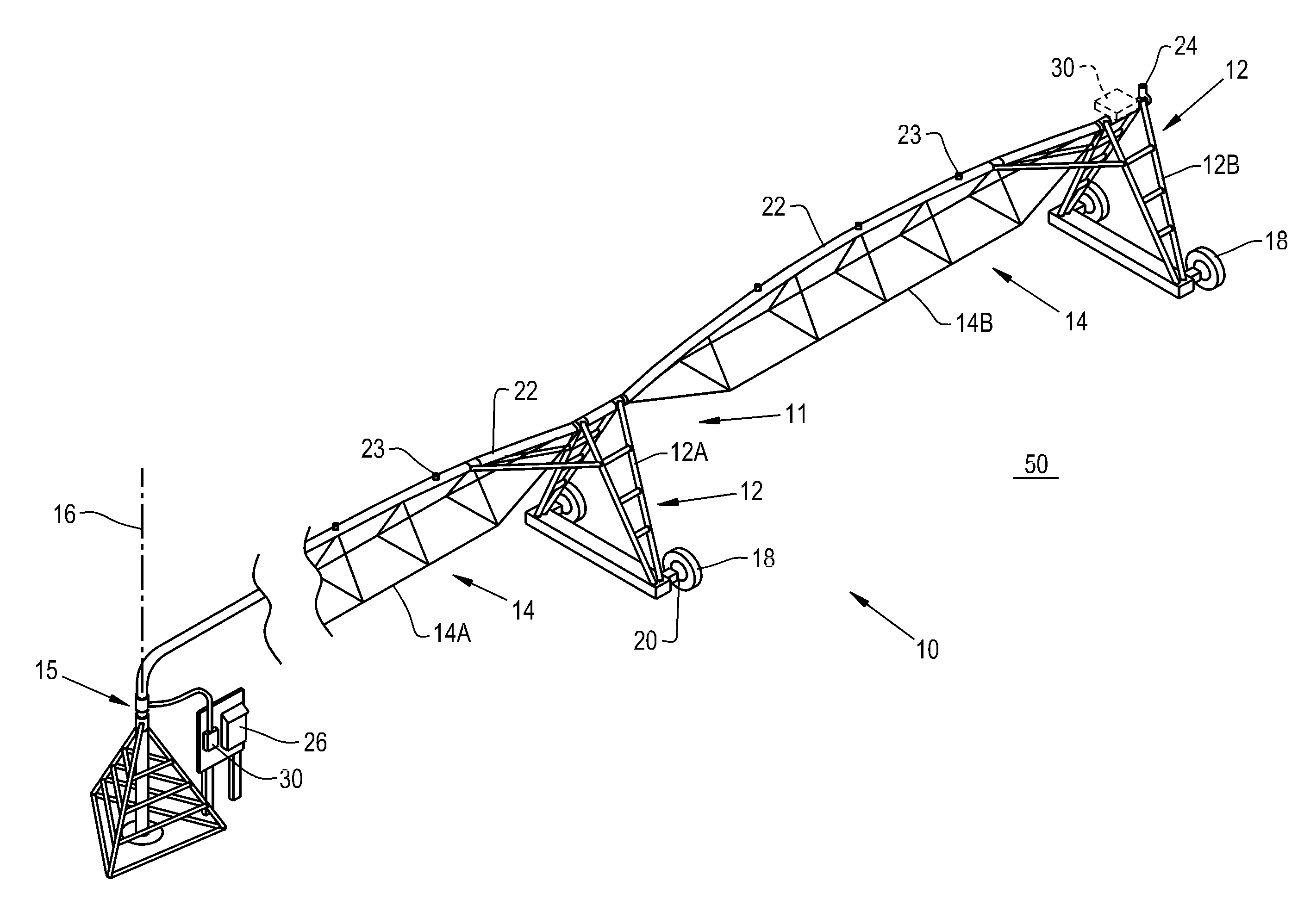
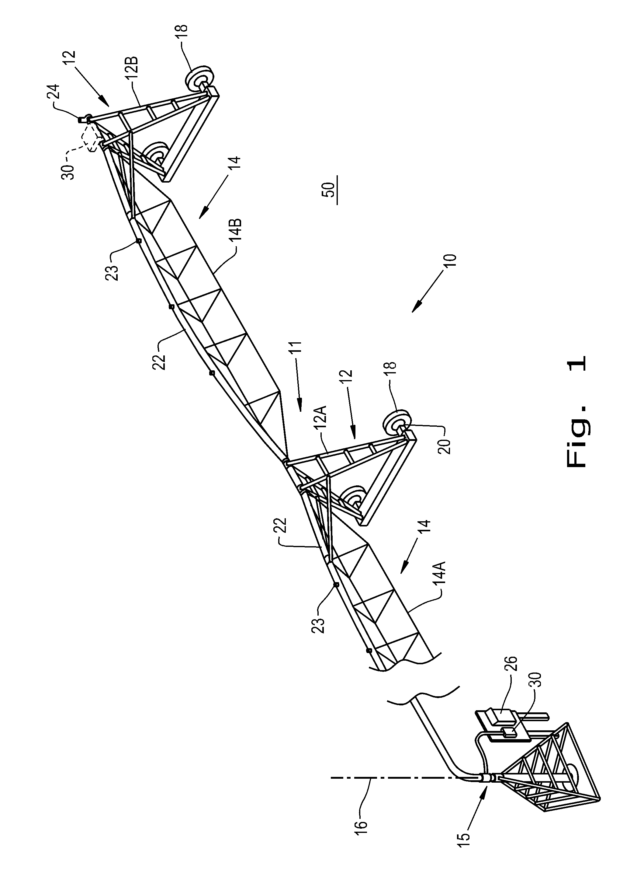
[0018]Referring now to FIG. 1, there is shown an example of a central pivot irrigation system 10 which generally includes a center anchor frame 15, a framework 11, fluid conduits 22, a control panel 26, and an offsite irrigation controller 30. The framework 11 generally includes mobile support towers 12 and truss-type support sections 14. The radially inner truss-type support section 14A is connected in between the center anchor frame 15 and the radially innermost mobile support tower 12A. To stretch a set length of the field 50, truss-type support sections 14 connected to mobile support towers 12 are linked together in succession, and the succession ends with the radially outermost support tower 12B. Some irrigation systems include a foldable corner system in which the outermost truss-type support section 14B connected to the outermost support tower 12B is able to swivel relative to the preceding framework to which it connects. The mobile support towers are supported by wheels 18, ...


PUM


Abstract

A center pivot irrigation system including a framework, a fluid conduit supported by the framework, a plurality of fluid-emitting nozzles associated with the fluid conduit, and a central control panel. Further, the irrigation system has an offsite irrigation controller, including a fluid-pressure sensor for sensing the fluid pressure inside the fluid conduit and a digital compass for monitoring the orientation of the irrigation system as it rotates about the center pivot axis. The offsite irrigation controller also includes a remote transmitter for communicating to an offsite receiver and an electrical processing circuit coupled with the fluid-pressure sensor, the digital compass, and the remote transmitter. The electrical processing circuit receives an output signal from each of the fluid-pressure sensor and the digital compass, and controls the remote transmitter to transmit the operational status of the irrigation system to an offsite user.

Description

BACKGROUND OF THE INVENTION[0001]1. Field of the Invention[0002]The present invention relates to agricultural irrigation systems, and more particularly to a controller and method to remotely monitor and control irrigation systems.[0003]2. Description of the Related Art[0004]Mobile irrigation systems in the agricultural industry generally include a pressurized water system formed from elevated fluid conduits supported by mobile support towers on wheels interlocked with truss-type framework sections. The fluid conduits have a plurality of sprinkler heads, spray heads, drop nozzles, or other fluid-emitting devices along the fluid conduit, via fittings, drop lines, etc. These fluid conduits have access to a well or other sources of water and may also be coupled to another source of chemical products, for example fertilizers or pesticides. As the fluid is being emitted, in order to irrigate the various sections of the field, an electric or hydraulic motor typically drives the respective ...

Claims


Application Information

Patent Timeline
Patent Type & Authority Applications(United States)
IPC IPC(8): A01G25/09A01G25/16
CPCA01G25/16A01G25/092
Inventor LENNARD, KYLE J.LENNARD, KEITH M.
Owner LENNARD TECH LLC
Why Eureka
Try Eureka