Cardiac valve support device fitted with valve leaflets

a technology of valve leaflets and support devices, which is applied in the field of valve support devices, can solve the problems of loss of valve function, loss of function, and compromise of the functionality of native valve leaflets

Inactive Publication Date: 2016-04-21
MVALVE TECH
View PDF2 Cites 232 Cited by
  • Summary
  • Abstract
  • Description
  • Claims
  • Application Information

AI Technical Summary

Benefits of technology

[0005]The present invention provides an alternative solution to the challenge of maintaining valve function during two step support / valve implantation procedures. In addition, the valve support device provided by the present invention may also be used to maintain valve function for longer periods of time (e.g. in the order of several weeks), thereby enabling the implantation of the replacement valve to be delayed by such periods of time, following the initial deployment of the support device fitted with the valve leaflets. In other cases, the valve leaflets attached to the support device may be used to maintain valve function for even longer periods of time (e.g. over the course of several years), thereby itself acting as a replacement valve.

Problems solved by technology

Occasionally, the functionality of the native valve leaflets may become compromised during implantation of the valve support—for example, if the leaflets suffer mechanical damage when the support is manipulated into its working position within the anatomical valve annulus.
In such cases, there will be loss of valve function during the period of time that elapses between the cessation of native valve function and the implantation of the replacement valve.
This period of time is commonly ten minutes or longer, and the loss of function of, for example, the mitral valve for even much shorter periods of time would be expected to have very serious clinical consequences, such as potentially fatal acute pulmonary edema.

Method used


Image

  • Cardiac valve support device fitted with valve leaflets
  • Cardiac valve support device fitted with valve leaflets
  • Cardiac valve support device fitted with valve leaflets

Examples


Embodiment Construction

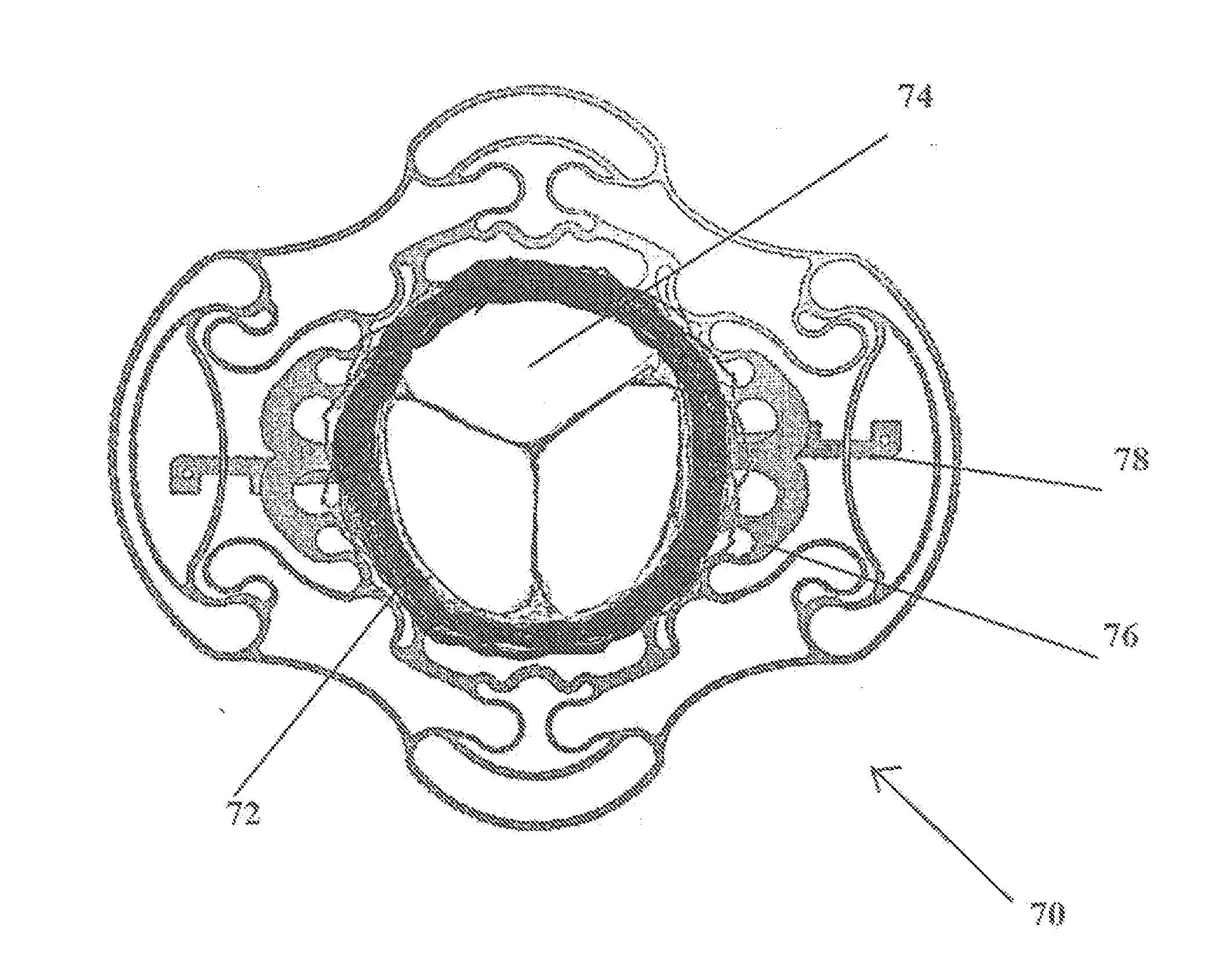
[0032]As explained hereinabove, the valve support device developed by the present inventions provides a solution to the challenge of maintaining valve function during two step support / valve implantation procedures, as well as for longer periods of time (e.g. in the order of several weeks), in cases in which the second stage of the procedure (i.e. implantation of the replacement valve) needs to be delayed by such periods of time.

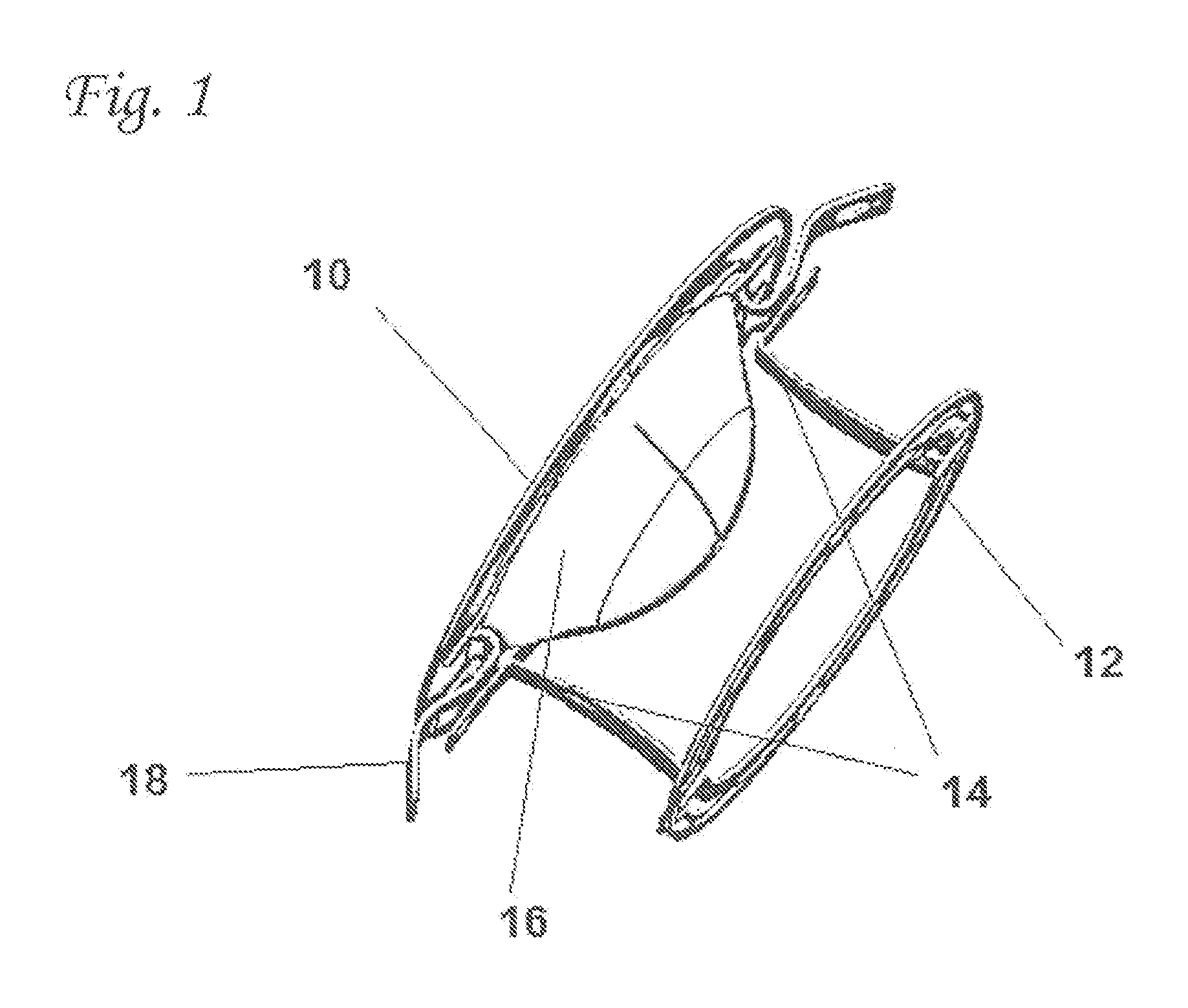
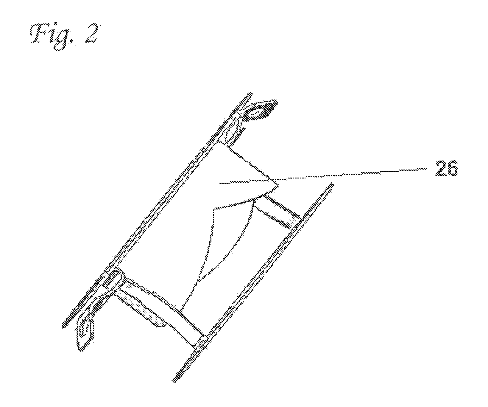
[0033]In the two-ring versions of the valve support device (as disclosed hereinabove), the one or more valve leaflets are attached to the upper ring of the valve support device. FIG. 1 shows, in perspective view, an example of such a device, having an upper support element 10 and a lower support element 12 mutually connected by two bridges 14. The valve leaflets 16 in this figure are shown their closed position. Two stabilizing arms 18 attached to upper support element 10 are also shown. The same embodiment, but with the valve leaflets 26 in their open positi...


PUM


Abstract

The present invention provides a cardiac valve support device adapted for endovascular delivery to a cardiac valve, wherein said support device comprises either a single support element with valve leaflets connected thereto or two interconnected support elements having valve leaflets connected to one of said two elements. The invention further encompasses a two-stage method for implanting a replacement cardiac valve, wherein the first stage comprises delivering a valve support device fitted with one or more valve leaflets to a location near a subject's cardiac valve, such that said valve leaflets fulfill the function previously fulfilled by the native valve.

Description

FIELD OF THE INVENTION[0001]The present invention is directed to valve support devices for use in two-stage cardiac valve replacement procedures. More specifically, the present invention provides valve support devices that are fitted with valve leaflets that may be used to maintain valve function prior to the deployment of a permanent replacement valve.BACKGROUND OF THE INVENTION[0002]Devices and methods for the two-stage implantation of replacement cardiac valves have been described in co-owned, co-pending international patent application no. PCT / US2011 / 050232 (published as WO 2012 / 031141). In the approach disclosed in this publication, a valve support is implanted within the region of a native valve annulus in a first stage, following which, in a second stage, a replacement cardiac valve is implanted within the internal space of said valve support. A key feature of the valve support disclosed in this publication is the presence and orientation of two bridging elements that mutuall...

Claims


Application Information

Patent Timeline
Patent Type & Authority Applications(United States)
IPC IPC(8): A61F2/24
CPCA61F2/2409A61F2/2412A61F2/2418A61F2250/0059A61F2250/0063
Inventor BUCHBINDER, MAURICEDUBI, SHAYTUBISHEVITZ, AMITGEVA, AVNER
Owner MVALVE TECH
Why Eureka
Try Eureka