Apparatus for injection molding of plastic material

Active Publication Date: 2016-04-21
INGLASS SPA
View PDF1 Cites 2 Cited by
  • Summary
  • Abstract
  • Description
  • Claims
  • Application Information

AI Technical Summary

Benefits of technology

[0013]possibility of use in molds of filling injection systems separated from the actuators, and therefore simpler and cheaper;
[0014]greater rigidit

Problems solved by technology

These solutions, although advantageous, do not allow the complete suppression of the thermal effects to which the electric motors are subjected to, due to the high temperatures of the distributor, except through the conditioning system of the backing plate of the mold, to ensure efficient cooling of the electric motors.
The electric motors are typically housed in seats provided in the

Method used


Image

  • Apparatus for injection molding of plastic material
  • Apparatus for injection molding of plastic material
  • Apparatus for injection molding of plastic material

Examples


Embodiment Construction

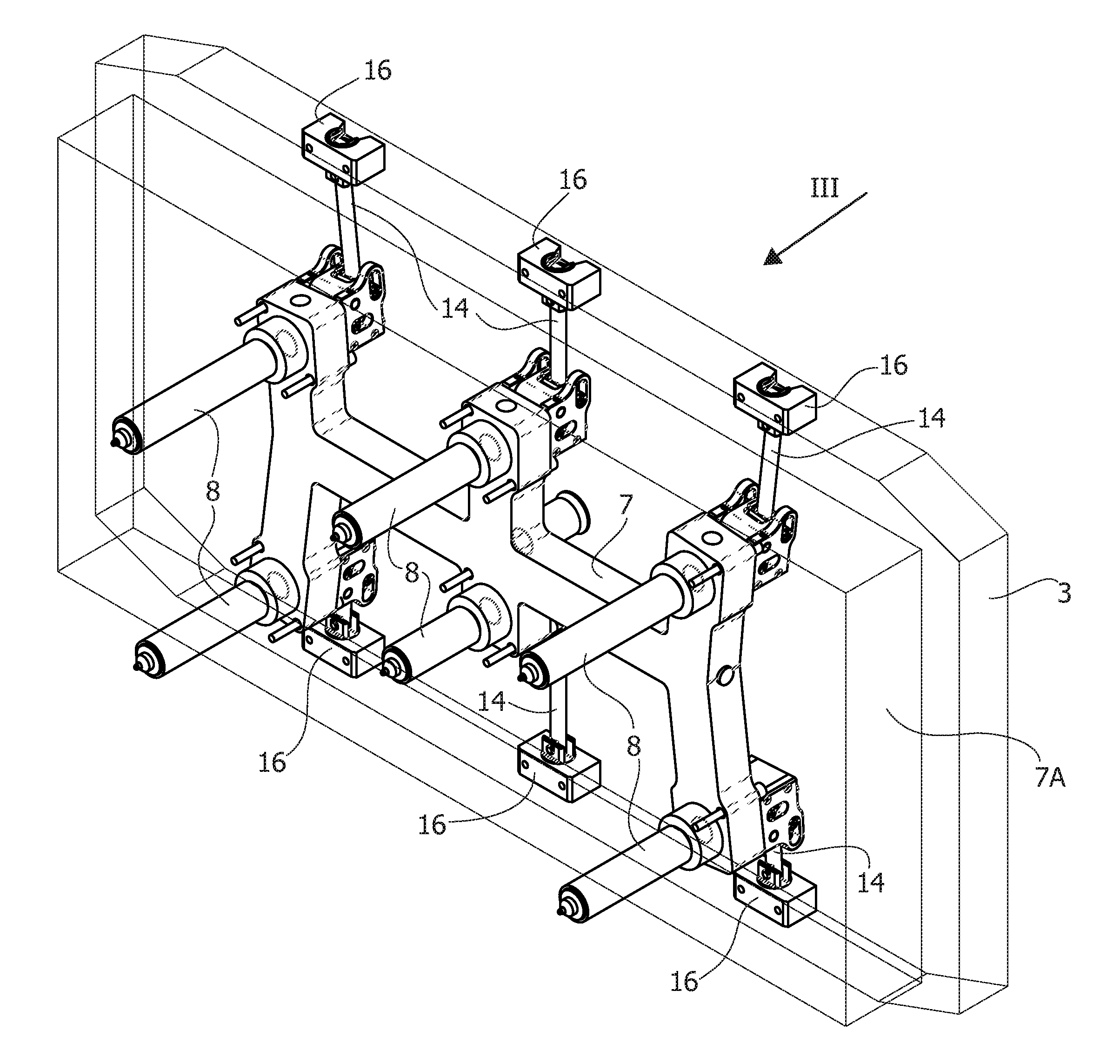
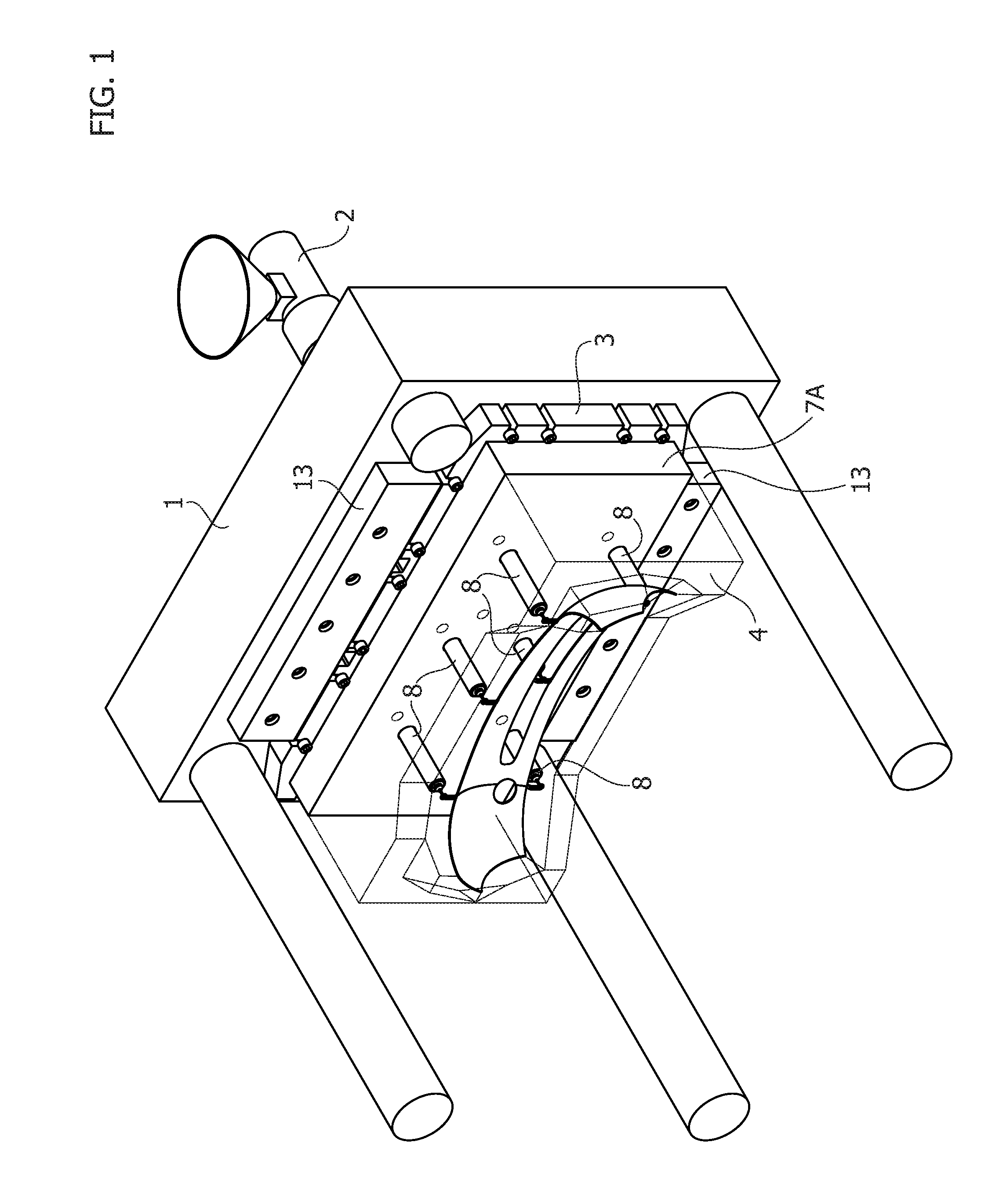
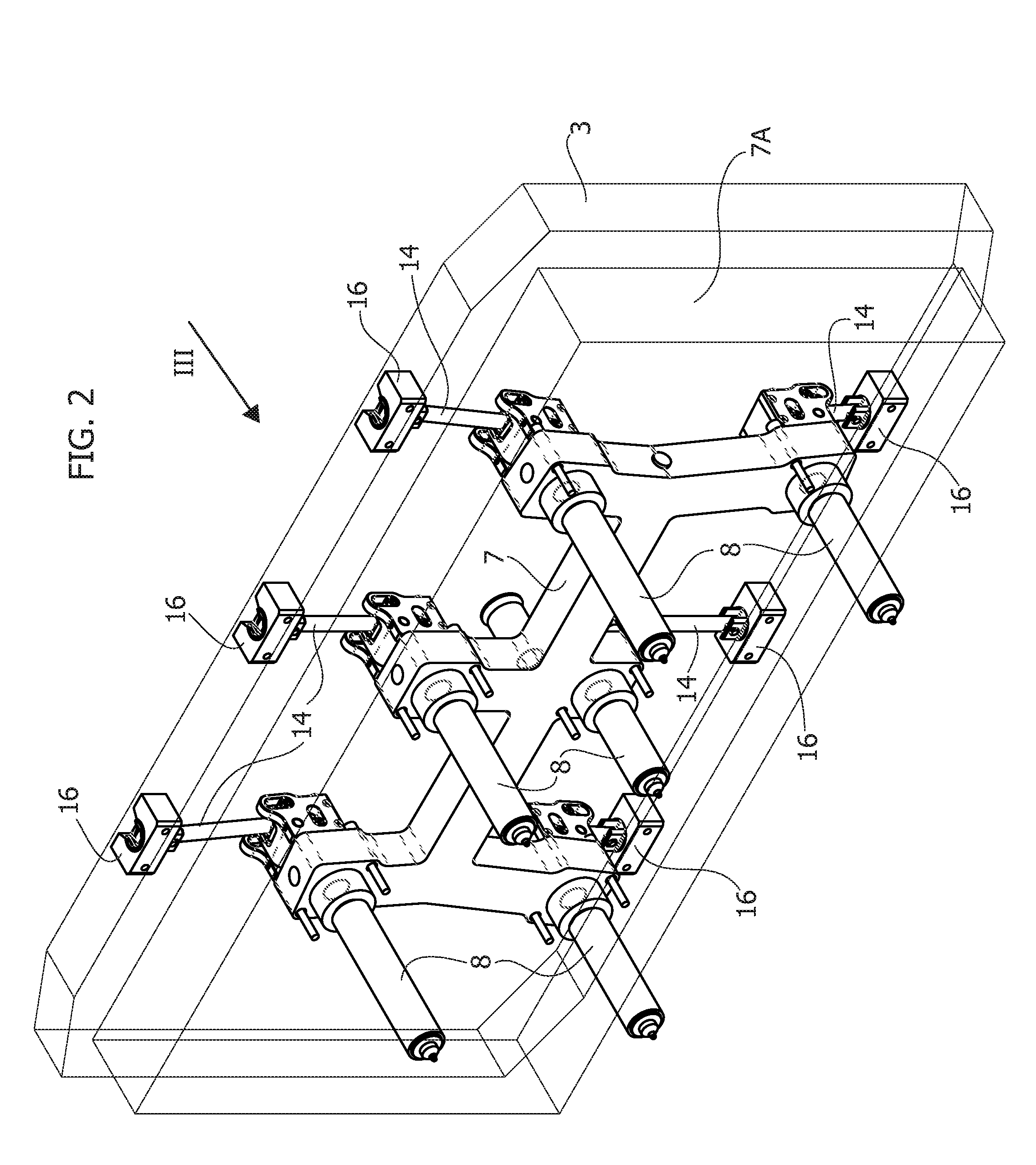
[0037]FIG. 1 schematically shows the essential components of an apparatus for injection molding of plastic materials according to a first embodiment of the invention. In a manner generally known per se, the apparatus comprises an injection machine platen 1, fixed or movable, connected to a plasticization unit partially indicated by 2, for supplying the plastic material to be injected. A backing plate or clamping plate 3 is fixed to the injection machine platen 1 of a mold 4, whose matrix is represented schematically. The plastic material in the fluid state, coming from the plasticization unit 2, is fed through a hole 5 (FIG. 5) of the injection machine platen 1 and a hole 6 of the backing plate 3, to a distributor or hot runner 7, connected to the backing plate 3 through a plate of the distributor 7A (“manifold plate”). The distributor 7 bears one, or as in the case of the example illustrated, a plurality of injectors 8 for injecting the plastic material into the cavity of the mold ...


PUM

PropertyMeasurementUnit
Lengthaaaaaaaaaa
Pressureaaaaaaaaaa

Abstract

An apparatus for injection molding of plastic materials includes an injection machine platen, a mold including a backing plate for securing the mold to the injection machine platen, a distributor of the plastic material to be injected adjacent to the backing plate and bearing at least one injector including a nozzle within which a pin valve is axially movable, and a respective electric actuator with associated transmission to operate the displacement of the pin valve between a closed position and an open position. The transmission includes a variable-length connecting rod.

Description

FIELD OF THE INVENTION[0001]The present invention relates to apparatuses for injection molding of plastic materials including an injection machine platen and a mold with a backing or clamping plate for securing the mold to the injection machine platen, a distributor of the plastic material to be injected, bearing at least one injector including a nozzle within which a pin valve is axially displaceable, and a or a respective actuator to operate the displacement of the pin valve between a closed position and an open position to enable fluid plastic material under pressure to flow from the distributor to the cavity of the mold.[0002]In particular, the invention relates to such a molding apparatus in which the operation of the pin valve of the or of each injector is achieved through one or a respective rotary electric motor with associated transmission to convert rotation of the electric motor shaft into a translation of the pin valve.STATE OF THE PRIOR ART[0003]The use of electric moto...

Claims


Application Information

Patent Timeline
IPC IPC(8): B29C45/23
CPCB29C45/231B29C45/07B29C45/1858B29C45/22B29C45/30B29C2045/304H02N2/028B29C45/1744B29C45/281B29C2045/282B29C2045/2824
Inventor BAZZO, MAURIZIO
Owner INGLASS SPA
Why Eureka
Try Eureka