
Ultrasonic horn, welder provided therewith, and method of producing disposable diaper using ultrasonic horn

Active Publication Date: 2016-04-21
ZUIKO CORP
View PDF2 Cites 11 Cited by
  • Summary
  • Abstract
  • Description
  • Claims
  • Application Information

AI Technical Summary

Benefits of technology

The present invention provides an ultrasonic horn that can increase output amplitude. Also, the invention provides a welder with the ultrasonic horn and a method of producing disposable diapers using the ultrasonic horn.

Problems solved by technology

The continuous body includes a nonwoven fabric sheet, a waterproof sheet and an elastic body, and the thickness dimension of the overlap portion of the continuous body is large and uneven.

Method used


Image

  • Ultrasonic horn, welder provided therewith, and method of producing disposable diaper using ultrasonic horn
  • Ultrasonic horn, welder provided therewith, and method of producing disposable diaper using ultrasonic horn
  • Ultrasonic horn, welder provided therewith, and method of producing disposable diaper using ultrasonic horn

Examples


first embodiment

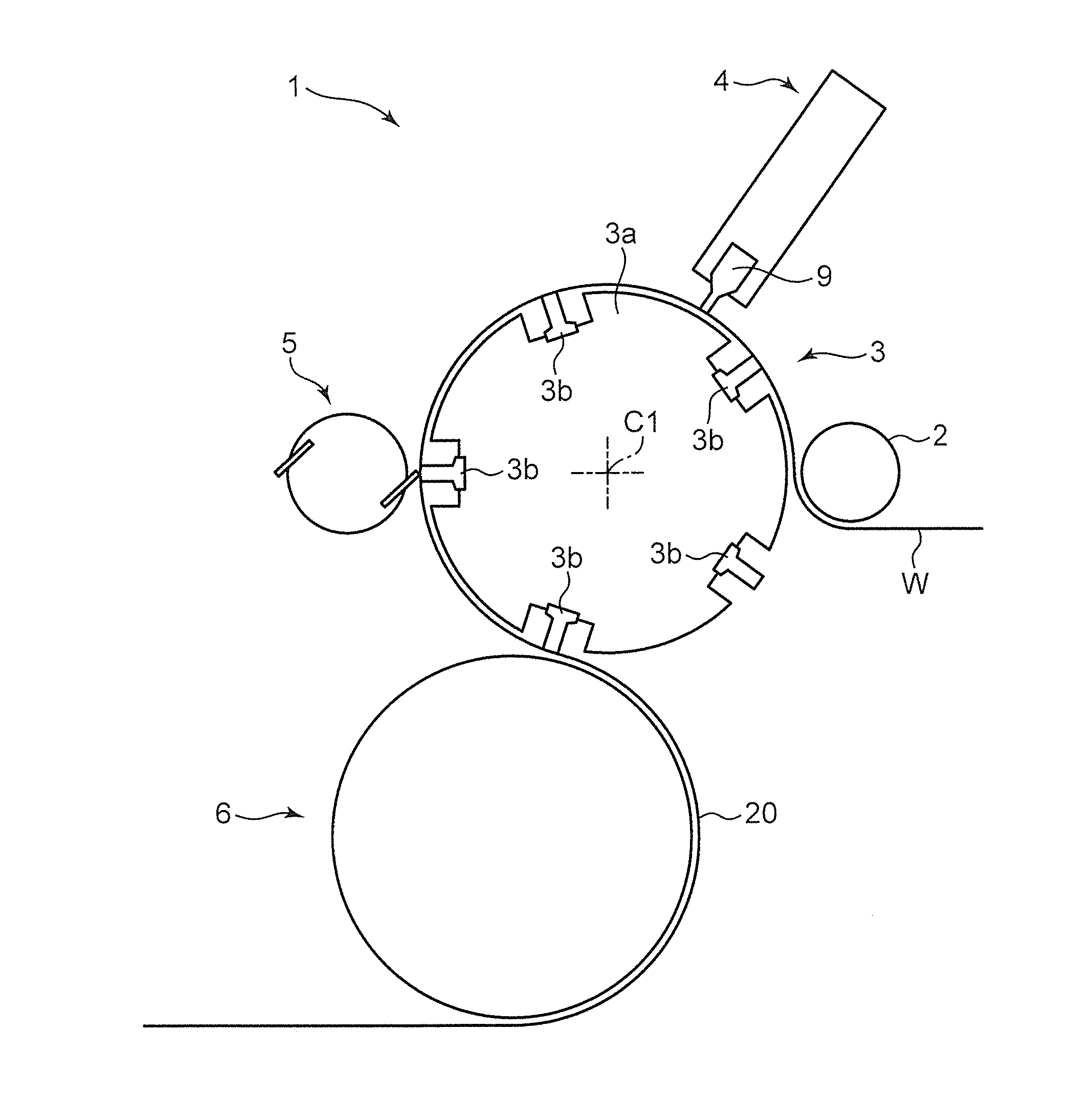
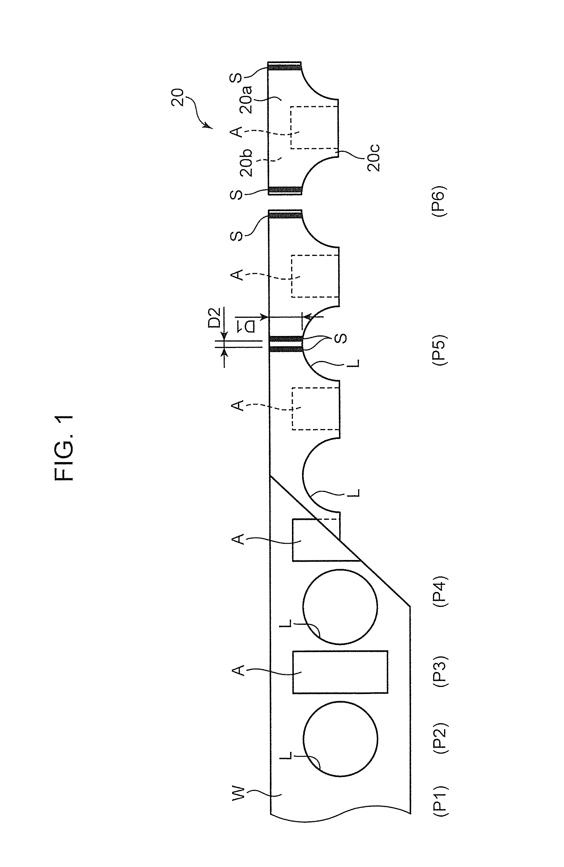
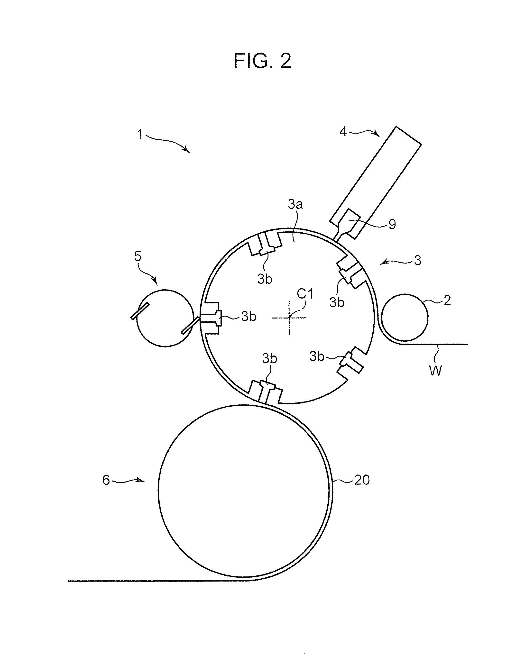
[0049]An explanation follows next, with reference to FIG. 2, on a welding device 1, that carries out the welding step P5 and the cutting step P6.

[0050]The welding device 1 includes an introduction roller 2 that introduces the sheet W undergone the fold-in-half step P4; a drum 3 that transports the sheet W introduced by the introduction roller 2; a welder 4 that welds the sheet W between the drum 3 and the welder 4; a rotary cutter 5 that cuts the sheet W between the drum 3 and the rotary cutter 5; and a lead-out roller 6 that leads the sheet W out of the drum 3.

[0051]The drum 3 can rotate counter-clockwise, in FIG. 2, about a rotation center C1. The drum 3 includes a drum body 3a having an outer peripheral surface onto which the sheet W can be sucked, and five anvils 3b that are provided in recesses sunk from the outer peripheral surface of the drum body 3a, and that support, from inward, the sheet W that is sucked onto the drum body 3a.

[0052]The anvils 3b are disposed at equal in...

third embodiment

[0086]the present invention will be explained next with reference to FIG. 6 to FIG. 8.

[0087]In a welding device 30 of the third embodiment, the ultrasonic horns 9 are provided inside a rotary drum 35 (side close to the center), and anvils 38 are provided outside the rotary drum 35 (far side from the center), such that the anvils 38 can slide with respect to the ultrasonic horns 9.

[0088]The purpose of the welding device 30 is to ultrasonically weld the sheet W that is introduced via an introduction roller 50 after being folded in half in the fold-in-half step P4, and to feed the welded sheet W to the cutting step P6, via a lead-out roller 51.

[0089]As illustrated in FIG. 6 and FIG. 7, specifically, the welding device 30 includes a drive shaft support member 31, a cam drum 32 fixed to the drive shaft support member 31, a cam follower 33 provided inside a cam groove 32a of the cam drum 32, a drive shaft 34 rotatably supported with respect to the drive shaft support member 31 about a rot...


PUM

PropertyMeasurementUnit
Lengthaaaaaaaaaa
Widthaaaaaaaaaa
Mechanical propertiesaaaaaaaaaa

Abstract

Provided is an ultrasonic horn, the output amplitude of which can be significantly increased. An ultrasonic horn includes an input-side end section that has an input surface that receives ultrasonic vibration, and an output-side end section having an output surface that outputs ultrasonic vibration to a sheet. The output-side end section has a dimension, in the length direction, over which a side edge portion of a front abdominal section and a side edge portion of a rear dorsal section can be welded in the longitudinal direction, and is branched in a width direction that is perpendicular to the length direction by a slit that extends in the length direction. A pair of surfaces of the output-side end section, positioned on both sides of the slit, functions as the output surface through which the ultrasonic vibration is output.

Description

TECHNICAL FIELD[0001]The present invention relates to an ultrasonic horn that is used in ultrasonic welding, a welder provided with the ultrasonic horn, and a method of producing a disposable diaper using the ultrasonic horn.BACKGROUND ART[0002]Conventionally known disposable diapers include disposable diapers that include a front abdominal section disposed on the abdomen of the wearer, a rear dorsal section disposed on the buttocks of the wearer, and a crotch section that extends from the front abdominal section, passing between the legs of the wearer, up to the rear dorsal section.[0003]In this disposable diaper, both side edges of the front abdominal section and both side edges rear dorsal section are welded to each other in such a manner that the front abdominal section and the rear dorsal section are connected in the form of a ring.[0004]To produce a disposable diaper of this type, there is firstly prepared a continuous body in which constituent elements each constituted by con...

Claims


Application Information

Patent Timeline
IPC IPC(8): B29C65/00B29C65/78B29C65/08
CPCB29C66/81431B29C65/08B29L2031/4878B29C66/0326B29C65/7885B29C65/086B29C66/1122B29C66/232B29C66/431B29C66/7294B29C66/81435B29C66/82263B29C66/8322B29C66/83511B29C66/83541A61F13/15739A61F13/15747A61F13/15804A61F2013/15821B29C66/81465B29C66/433B29C65/087B29C66/8362B29C65/7847B29C66/71B29C66/8412B29K2023/06B29K2023/12
Inventor FUJITA, YUKIHIKONAKAMURA, HIDEYUKI
Owner ZUIKO CORP
Learn More