Separated super-magnetostrictive telescopic rotary ultrasonic vibration head

A giant magnetostrictive and ultrasonic vibrating head technology, applied in the direction of the fluid using vibration, can solve the problems of limiting the spindle speed, fast sliding wear of the slip ring, unfavorable tool holder integration, etc., to increase the output power and output amplitude, The effect of reducing overall mass and improving transmission efficiency

Active Publication Date: 2013-05-01
深圳市青鼎装备有限公司
View PDF6 Cites 33 Cited by
  • Summary
  • Abstract
  • Description
  • Claims
  • Application Information

AI Technical Summary

Problems solved by technology

The main disadvantages of using conductive slip rings are: (1) the sliding wear of the slip ring is fast, the service life is short, and it needs to be replaced frequently, and the replacement is troublesome; (2) the wire of the slip ring is exposed, easy to catch fire, and has a certain (3) The speed of the slip ring should not be too high, which limits the speed of the spindle, which is not good for the application environment of high speed
At present, there is no giant magnetostrictive transducer designed for rotary ultrasonic machining. The common design form has many unreasonable features for rotary ultrasonic machining. For example, the coil that generates the alternating magnetic field is designed as one with the giant magnetostrictive rod. , conductive slip rings still need to be used in rotating applications; and if the structural design is unfavorable to the integration of tool holders, a large change is required before it can be applied to rotating ultrasonic machining

Method used


Image

  • Separated super-magnetostrictive telescopic rotary ultrasonic vibration head
  • Separated super-magnetostrictive telescopic rotary ultrasonic vibration head
  • Separated super-magnetostrictive telescopic rotary ultrasonic vibration head

Examples


Embodiment Construction

[0026] Embodiments of the present invention are described in detail below, examples of which are shown in the drawings, wherein the same or similar reference numerals designate the same or similar elements or elements having the same or similar functions throughout. The embodiments described below by referring to the figures are exemplary and are intended to explain the present invention and should not be construed as limiting the present invention.

[0027] In describing the present invention, it should be understood that the terms "center", "longitudinal", "transverse", "length", "width", "thickness", "upper", "lower", "front", " The orientation or positional relationship indicated by "rear", "left", "right", "vertical", "horizontal", "top", "bottom", "inner" and "outer" are based on the orientation or position shown in the drawings The positional relationship is only for the convenience of describing the present invention and simplifying the description, but does not indica...


PUM


Abstract

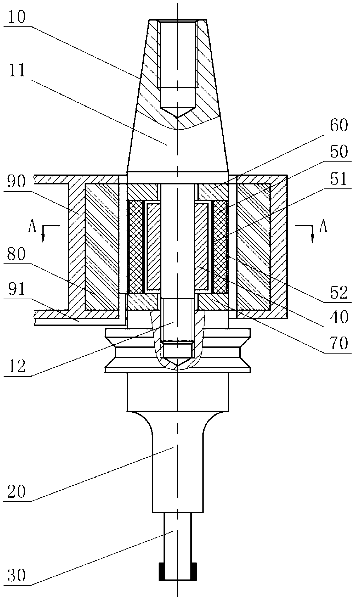
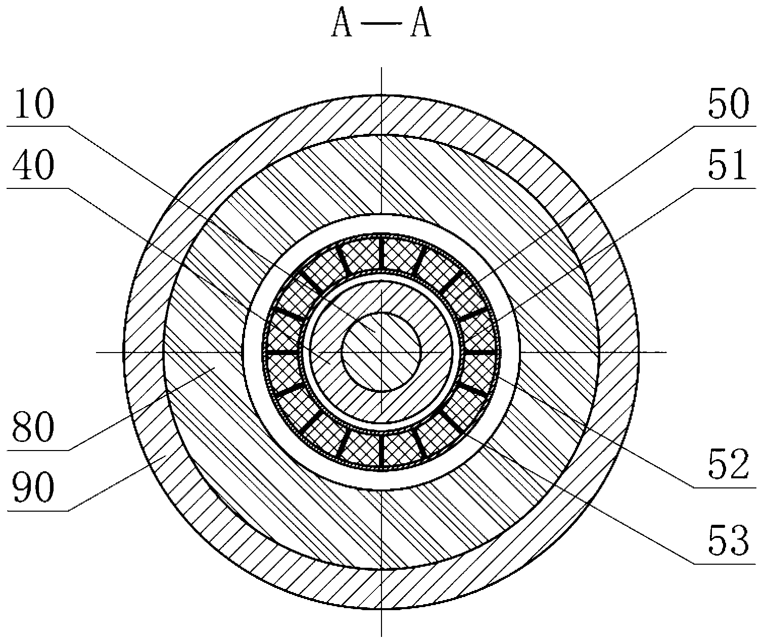
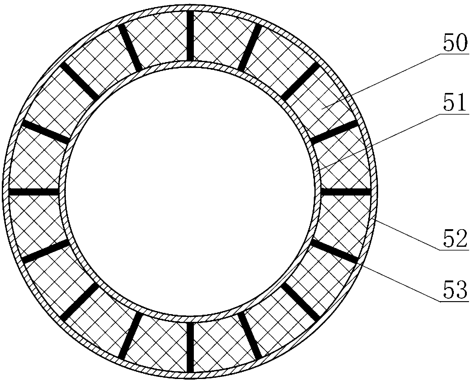
The invention discloses a separated super-magnetostrictive telescopic rotary ultrasonic vibration head which comprises a cutter handle, a variable amplitude rod, a cutter, a permanent magnet body, a super-magnetostrictive telescopic rod, a first magnetic conduction piece and a second magnetic conduction piece, a coil and a coil support; the super-magnetostrictive telescopic rod is sleeved on the permanent magnetic body and coaxial with the permanent magnetic body; a filling gap is formed between the super-magnetostrictive telescopic rod and the permanent magnetic body; the coil is sleeved on the super-magnetostrictive telescopic rod; ultrasonic alternating current is fed into the coil to generate an alternating magnetic field so as to drive the super-magnetostrictive telescopic rod to generate ultrasonic longitudinal vibration; and the coil support is arranged on the periphery of the coil for installing the coil. According to the ultrasonic vibration head provided by the embodiment of the invention, the coil and the cutter handle are separated, so that the energy transmission efficiency is improved while the non-contact transmission of ultrasonic energy is realized, and the output power and the output amplitude are increased under the same conditions.

Description

technical field [0001] The invention relates to the technical field of ultrasonic precision machining, in particular to a separated giant magnetostrictive rotating ultrasonic vibration head. Background technique [0002] In the design and manufacture of rotary ultrasonic processing equipment, the commonly used method is to use piezoelectric ceramic sheets as electrical-mechanical energy conversion elements, and use conductive slip rings between the ultrasonic generator and piezoelectric ceramic transducers to transfer electrical energy from The stationary part (sonicator) transmits out to the rotating part (piezo transducer). The main disadvantages of using conductive slip rings are: (1) the sliding wear of the slip ring is fast, the service life is short, and it needs to be replaced frequently, and the replacement is troublesome; (2) the wire of the slip ring is exposed, easy to catch fire, and has a certain (3) The speed of the slip ring should not be too high, which limi...

Claims


Application Information

Patent Timeline
Patent Type & Authority Applications(China)
IPC IPC(8): B06B1/08B23P9/00
Inventor 冯平法张建富申昊吴志军郁鼎文
Owner 深圳市青鼎装备有限公司
Why Eureka
Try Eureka