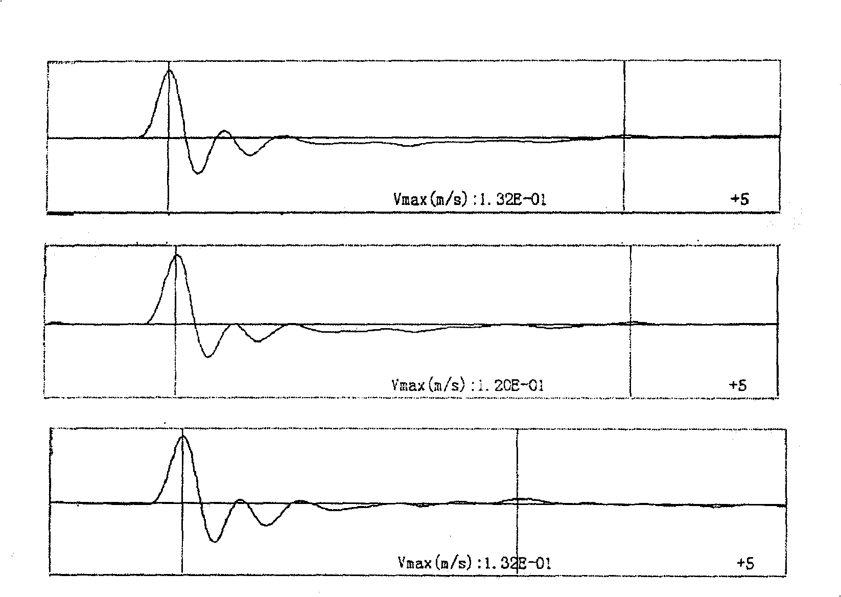
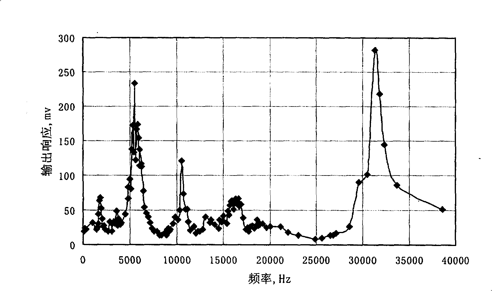
Magnetostrictive transducer used for sound wave nondestructive examination
A non-destructive testing and magnetostrictive technology, which is used in material analysis, instruments, and measuring devices using sonic/ultrasonic/infrasonic waves. performance uncertainty and other issues to achieve the effect of stable performance
- Summary
- Abstract
- Description
- Claims
- Application Information
AI Technical Summary
Problems solved by technology
Method used
Image
Examples
Embodiment 1
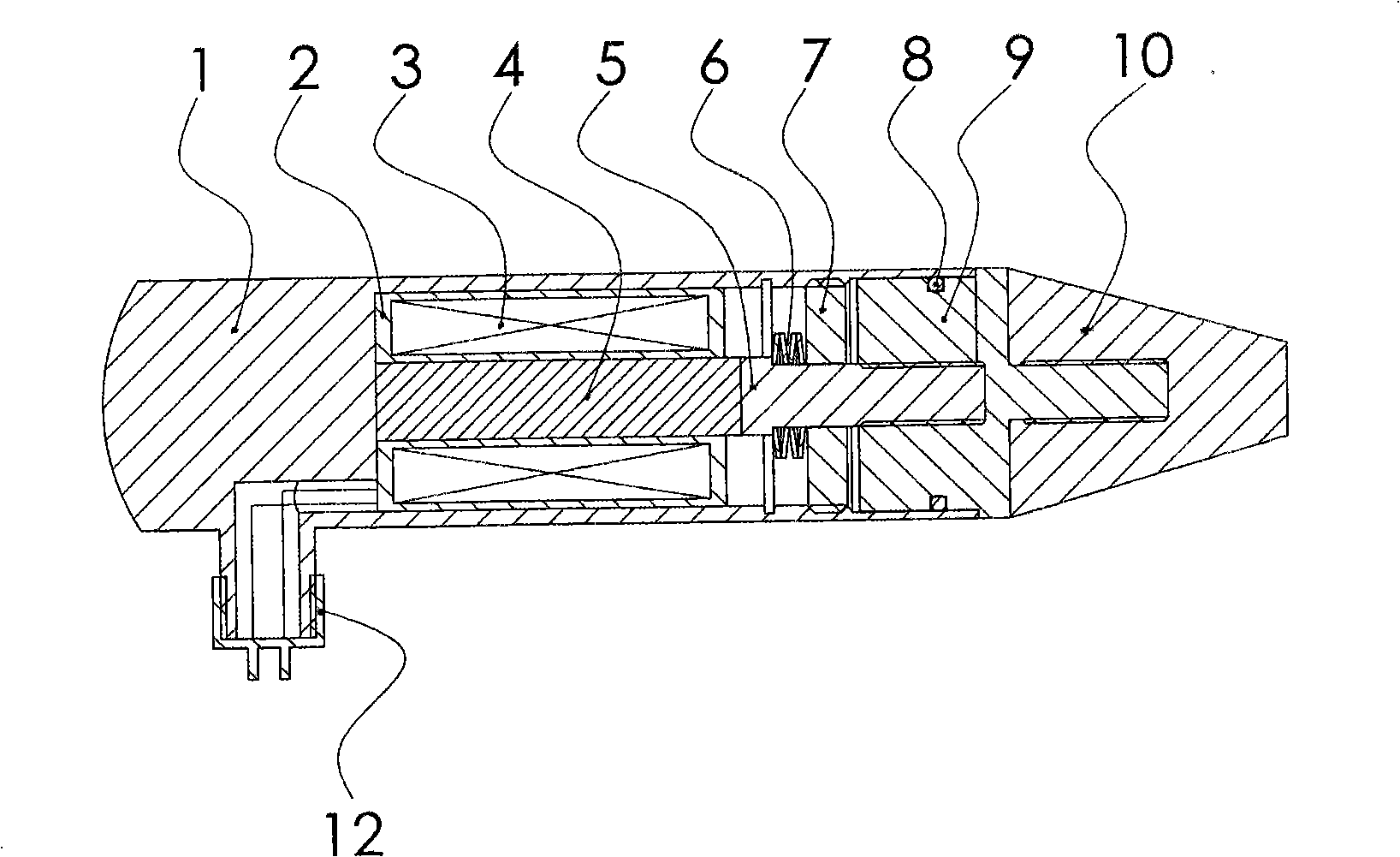
[0043] figure 1A schematic structural diagram of an embodiment of the transducer of the present invention is shown. The transducer consists of a shell 1 with one end open (upper end) and one end closed (bottom end), in which the electromagnetic drive coil 3 and the magnetostrictive material rod 4 are put into the shell, and are fixed on the shell with resin potting 2 the bottom end of the bottom; one end has a step and the other end has an output connecting rod 5 with external threads, and the middle sleeve is provided with a pre-tightening spring 6 and a pre-tightening lock nut 7 with a through hole in the center. 4 connection, the threaded end is connected with the vibration output block base 9; the O-shaped sealing rubber ring 8 is installed in the sealing groove of the vibration output block base 9, and forms a sealing structure with the inner side of the housing 1; the front end 10 of the vibration output block is in contact with the vibration output block The output blo...
Embodiment 2
[0045] figure 2 And Fig. 3 shows another embodiment structure and exploded view of the transducer of the present invention. The transducer consists of a shell 1 with one end open (upper end) and one end closed (bottom end), in which the electromagnetic drive coil 3 and the magnetostrictive material rod 4 are put into the shell, and are fixed in the shell with resin potting 2 the bottom end of the bottom; one end has a step and the other end has an output connecting rod 5 with external threads, and the middle sleeve is provided with a pre-tightening spring 6 and a pre-tightening lock nut 7 with a through hole in the center. 4 connection, the threaded end is connected with the vibration output block base 9; the O-shaped sealing rubber ring 8 is installed in the sealing groove of the vibration output block base 9, and forms a sealing structure with the inner side of the housing 1; the front end 10 of the vibration output block is in contact with the vibration output block The o...
Embodiment 3
[0047] Figure 4 A schematic structural diagram of the third embodiment of the transducer of the present invention is shown. The transducer consists of an open end
[0048] (upper end), a housing 1 with one end closed (bottom end), wherein the electromagnetic drive coil 3 and the magnetostrictive material rod 4 are packed into the housing, and are fixed on the bottom end of the housing with resin potting 2; one end has a step and the other The output connecting rod 5 with an external thread at one end is sleeved with a preload spring 6 and a preload lock nut 7 with a through hole in the center. The stepped end of the output connecting rod is connected to the magnetostrictive rod 4, and the threaded end is connected to the vibration output The block 9 is connected; the O-shaped sealing rubber ring 8 is installed in the sealing groove of the vibration output block 9, and forms a sealing structure with the inner side of the housing 1; there is a waterproof power supply card seat...
PUM
| Property | Measurement | Unit |
|---|---|---|
| flexural strength | aaaaa | aaaaa |
| diameter | aaaaa | aaaaa |
| diameter | aaaaa | aaaaa |
Abstract
Description
Claims
Application Information
 - R&D
- Intellectual Property
- Life Sciences
- Materials
- Tech Scout
- Unparalleled Data Quality
- Higher Quality Content
- 60% Fewer Hallucinations
Browse by: Latest US Patents, China's latest patents, Technical Efficacy Thesaurus, Application Domain, Technology Topic, Popular Technical Reports.
© 2025 PatSnap. All rights reserved.Legal|Privacy policy|Modern Slavery Act Transparency Statement|Sitemap|About US| Contact US: help@patsnap.com


