
Method and system for fabrication of custom made molds and concrete architectural components

a technology of custom-made molds and concrete, applied in the direction of dough dividing, dough shaping and dividing combination, buttons, etc., can solve the problems of high inefficiency of the process, construction rework, cost overrun, etc., and achieve the effect of reducing the cost of construction, and improving the quality of construction

Active Publication Date: 2016-04-21
BEYON 3D
View PDF4 Cites 32 Cited by
  • Summary
  • Abstract
  • Description
  • Claims
  • Application Information

AI Technical Summary

Benefits of technology

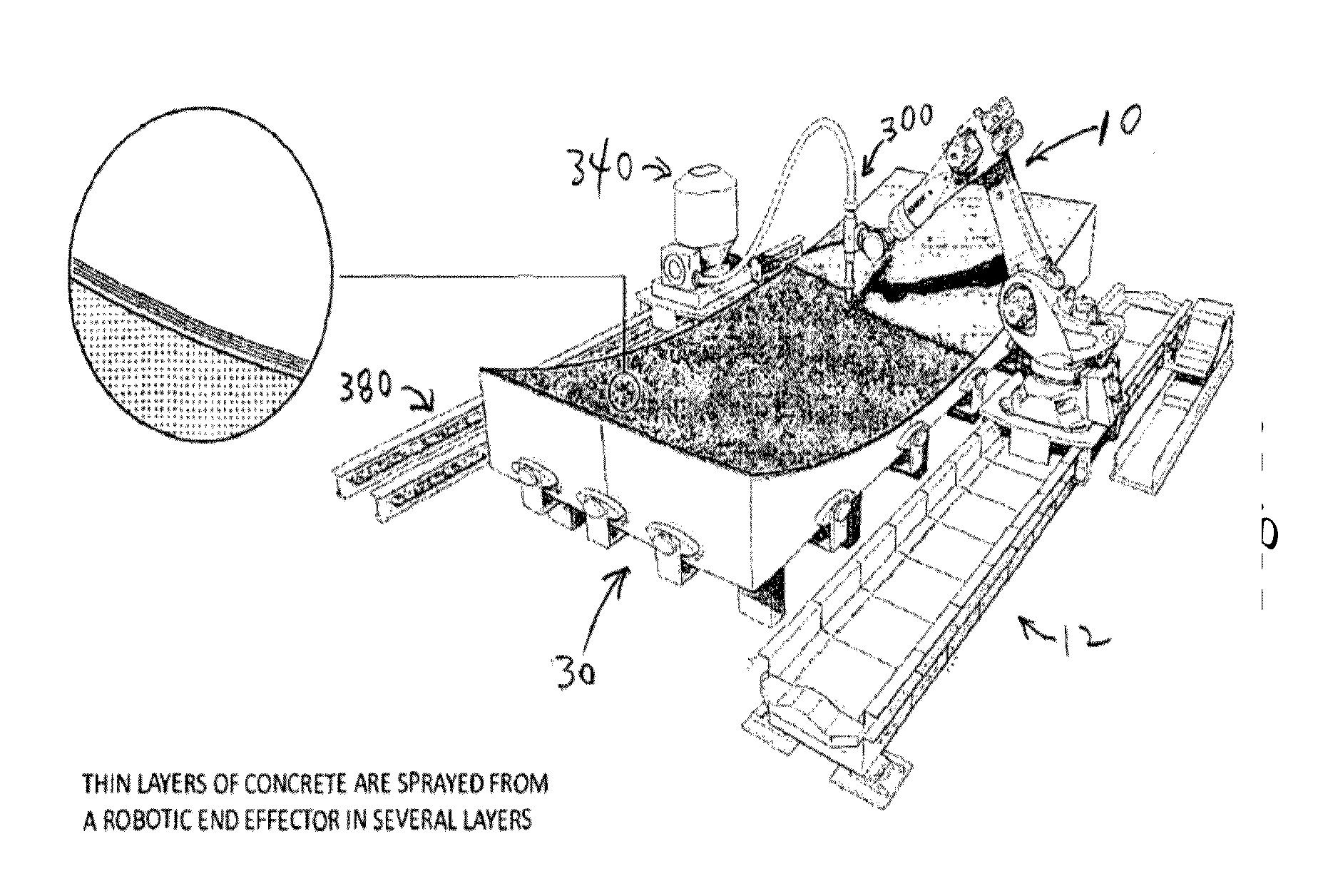
The invention provides a lightweight and strong layered concrete panel that can be sprayed on a polystyrene mold and formed into complex, non-conventional shells.

Problems solved by technology

This process is highly inefficient, as it wastes human resources and materials, frequently resulting in cost overruns, late delivery, and construction reworking.
The advent of 3D printing technology may seem promising, but current 3D technology suffers from problems of scale and quality of fabrication, as it employs additive printing processes through sequential layering of polymeric or thermoplastic materials.
Furthermore, 3D printing processes are generally not suitable for manufacturing large architectural structures or for creating cladding components on any architectural scale.
CNC machines impose severe restrictions on the geometry and material of the work pieces, however.
Increasingly, customers are demanding more complex and difficult to fabricate architectural structures, for example, structures with curvilinear shapes or are made of composite materials.
Thus, the fundamental limitations of digital fabrication technologies and mass production techniques currently known in the art limit the extent to which these methods can provide a solution to the problems outlined above.

Method used


Image

  • Method and system for fabrication of custom made molds and concrete architectural components
  • Method and system for fabrication of custom made molds and concrete architectural components
  • Method and system for fabrication of custom made molds and concrete architectural components

Examples


Embodiment Construction

[0073]In the following description, various aspects of the invention will be described. For the purposes of explanation, specific details are set forth in order to provide a thorough understanding of the invention. It will be apparent to one skilled in the art that there are other embodiments of the invention that differ in details without affecting the essential nature thereof. Therefore the invention is not limited by that which is illustrated in the figure and described in the specification, but only as indicated in the accompanying claims, with the proper scope determined only by the broadest interpretation of said claims.

[0074]As used herein, the term “architectural component” refers to any component that can be used in the construction of, or can be attached to, a building or structure. The term can be used to refer components that are functional as well as those that are purely decorative, as well as to panels of architectural material.

[0075]As used herein, the term “architec...


PUM

PropertyMeasurementUnit
Lengthaaaaaaaaaa
Timeaaaaaaaaaa
Thicknessaaaaaaaaaa

Abstract

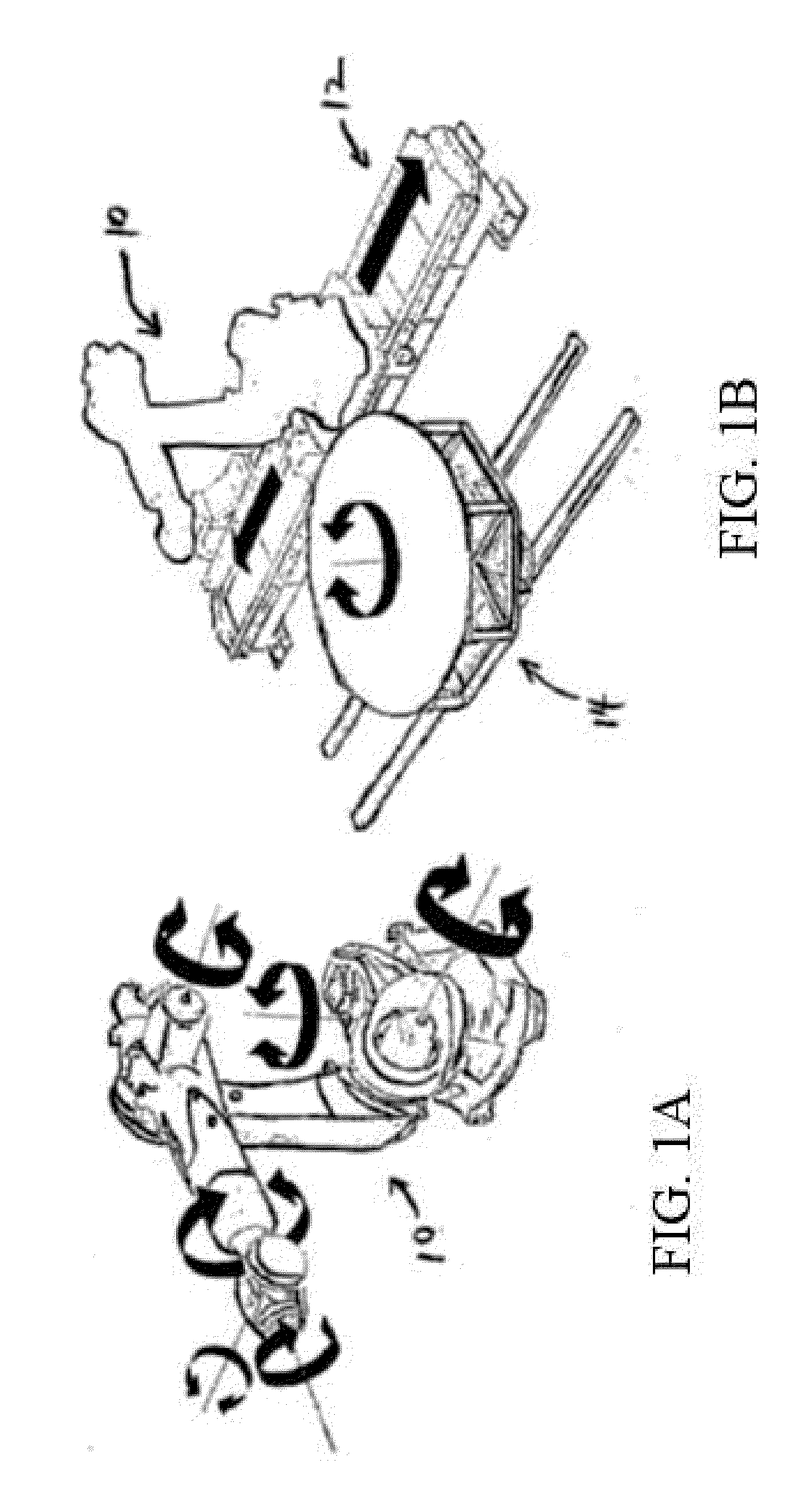
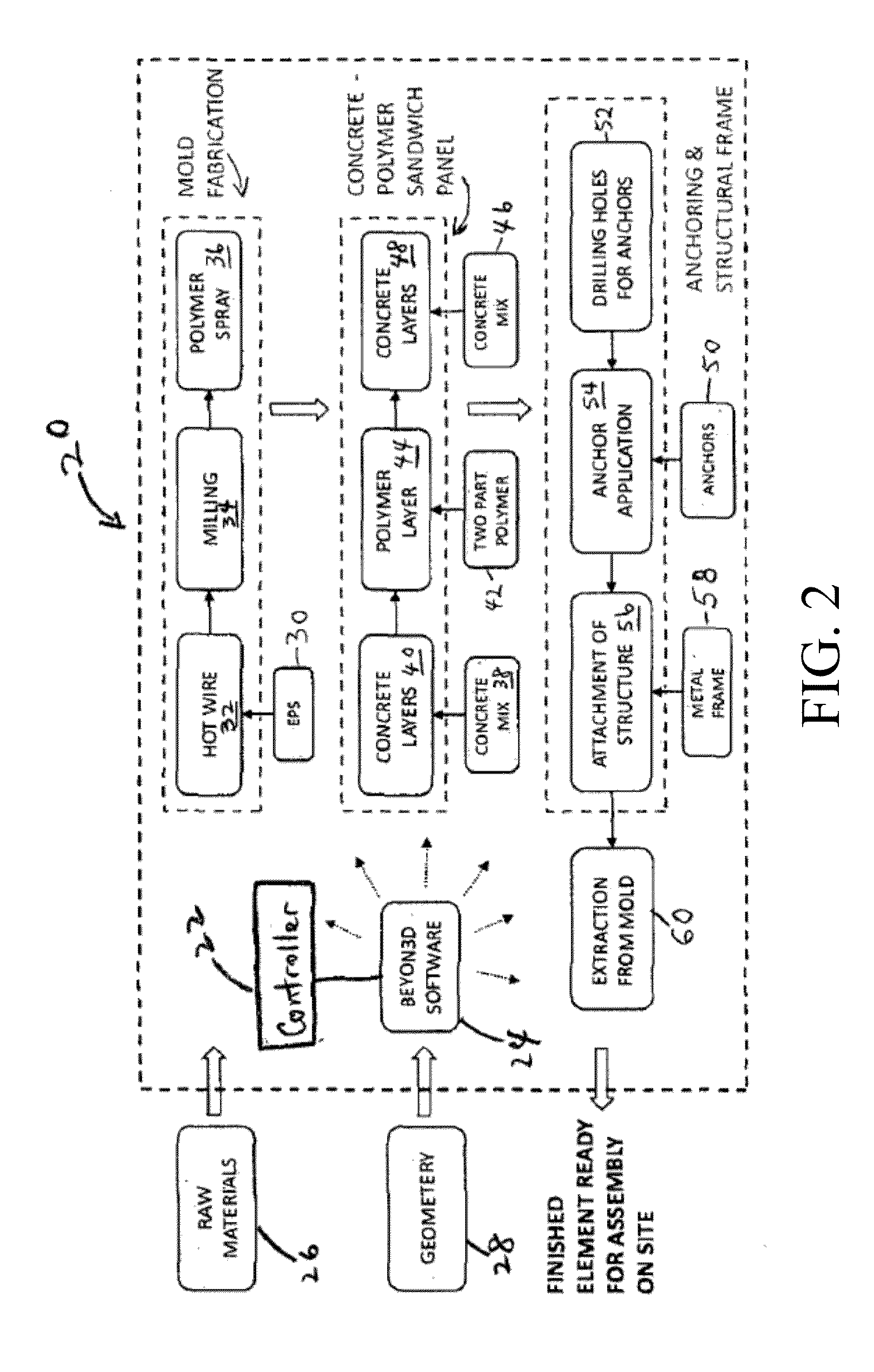
A method and system for constructing an architectural component from a three-dimensional form are disclosed. In a preferred embodiment, the system comprises a movable support table for supporting and moving a three-dimensional form; a multi-task robotic arm having a base end configured for controlled movement along a path proximate the support table and a distal end configured to extend, translate, and / or rotate relative to the base and to include an end effector for applying successive layers of material onto and / or removing material from a form on the support table; optionally, a linear rail to which said base is attached; and a computer processor for controlling a sequence of movements of the support table, the base, and the distal end of said multi-task robotic arm, and for controlling application or removal of material to or from the three-dimensional form to form an architectural component of a predetermined shape and dimension.

Description

REFERENCE TO RELATED APPLICATIONS[0001]This application claims priority from U.S. Provisional Patent Application No. 62 / 029,612, filed 28 Jul. 2014, which is hereby incorporated by reference in its entirety.FIELD OF THE INVENTION[0002]The present invention relates in general to construction of architectural components, and particularly to the use of computer controlled robotic arms for fabricating large-scale architectural concrete layered panels over polymeric forms.BACKGROUND OF THE INVENTION[0003]At present, the construction industry relies heavily on the use of on-site manual labor. This process is highly inefficient, as it wastes human resources and materials, frequently resulting in cost overruns, late delivery, and construction reworking. The advent of 3D printing technology may seem promising, but current 3D technology suffers from problems of scale and quality of fabrication, as it employs additive printing processes through sequential layering of polymeric or thermoplastic...

Claims


Application Information

Patent Timeline
IPC IPC(8): B29C69/00B05B7/26B05D1/02B26F3/12
CPCB29C69/001B26F3/12B05B7/26B29L2031/772B33Y30/00B33Y50/00B05D1/02B28B1/00B29C67/00B25J11/00B28B1/001B28C5/0875B33Y10/00
Inventor BERMAN, RAN
Owner BEYON 3D
Learn More