
Workload Partitioning Procedure for Null Message-Based PDES

a workload and null message technology, applied in the field of workload partitioning procedures for null message-based pdes, can solve the problems of inaccurate and quantitative performance, inability to identify the most critical task lps, conflicting two goals, etc., and achieve the effect of accurate evaluation of partitioning quality

Active Publication Date: 2016-04-21
INT BUSINESS MASCH CORP
View PDF0 Cites 0 Cited by
  • Summary
  • Abstract
  • Description
  • Claims
  • Application Information

AI Technical Summary

Benefits of technology

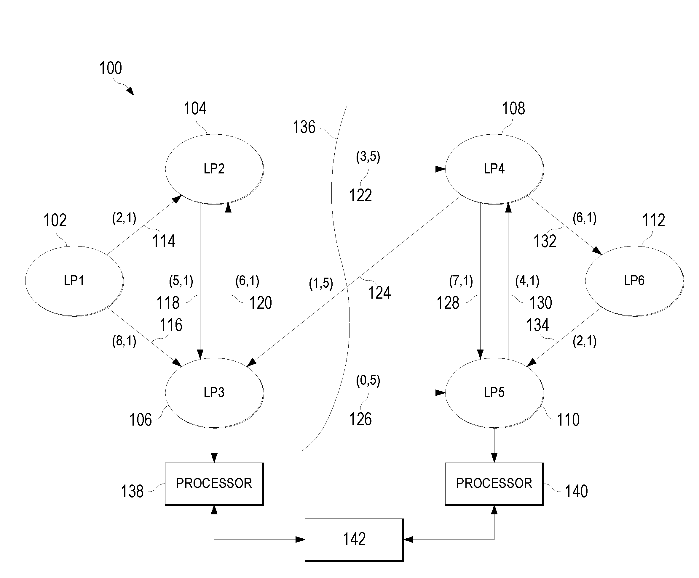
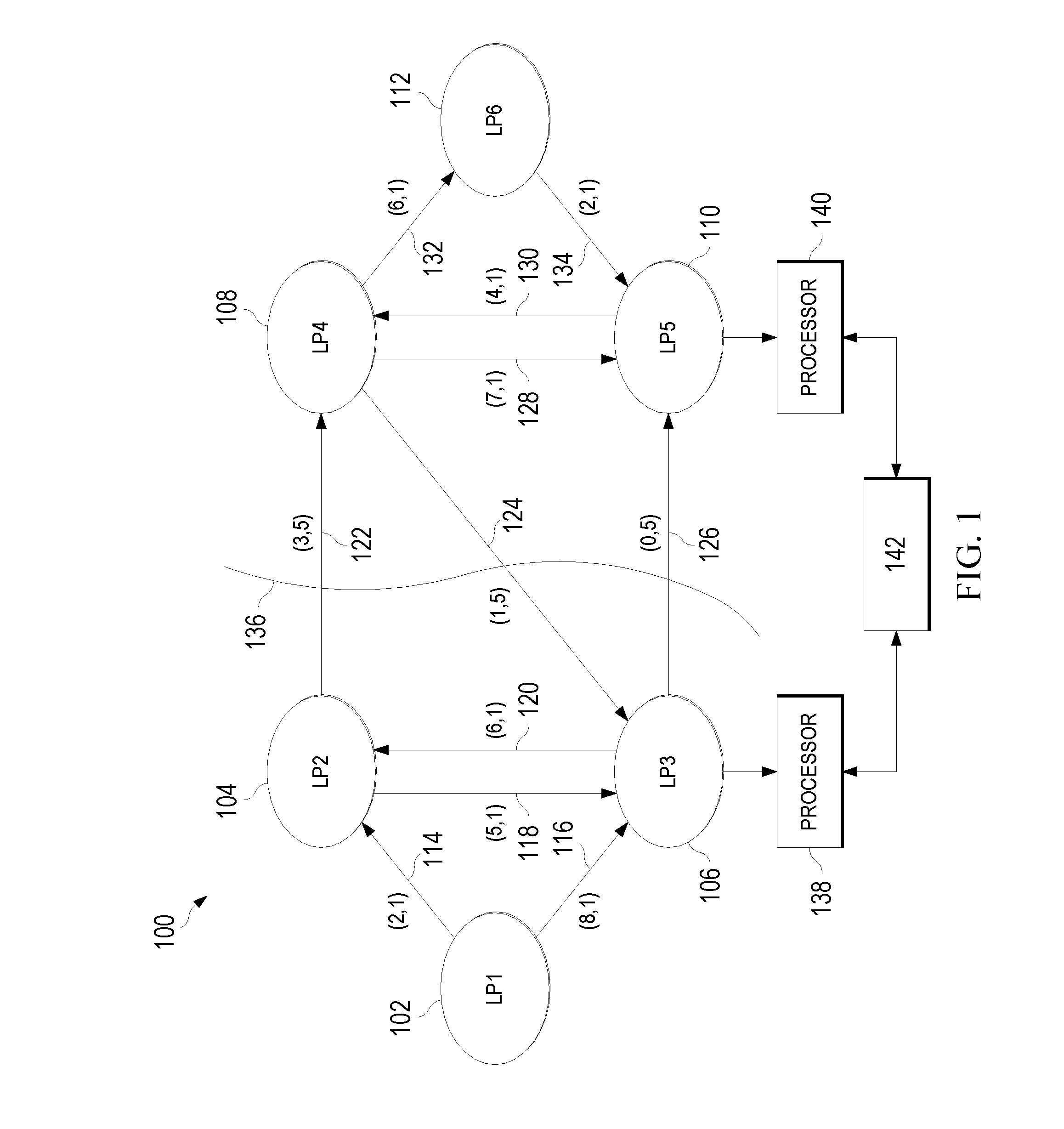
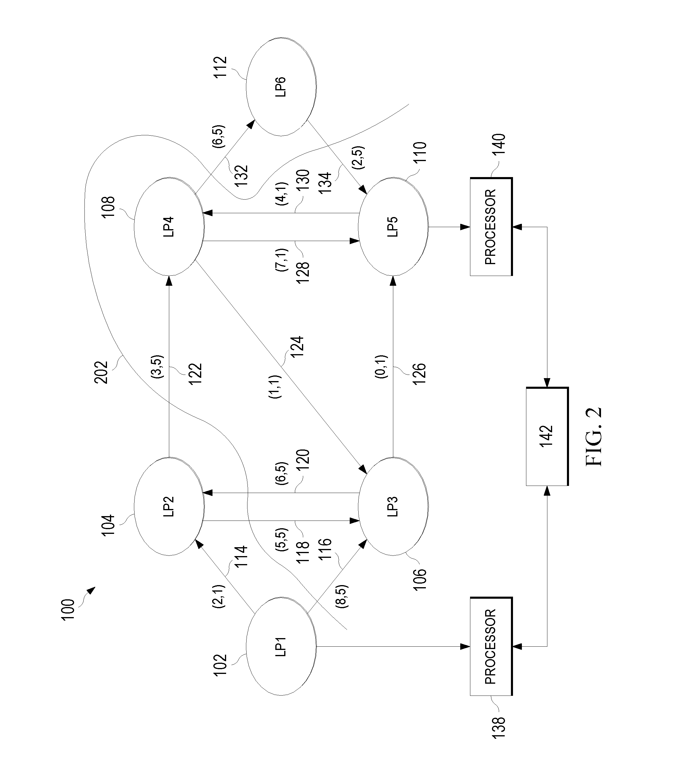
[0008]Embodiments of the invention present a generic partitioning approach, which uses an accurate performance evaluation model in its decision making process for PDES based on null message algorithms. By using this performance evaluation method, exact critical simulation tasks can be identified efficiently and prioritized accordingly in the partitioning process. Further, the performance evaluation method also gives the partitioner a system-level view of the impact of its decision process by enabling accurate evaluation of the partitioning quality in terms of the simulation performance.

Problems solved by technology

Yet these two goals are sometimes conflicting.
However, due to the lack of an accurate and quantitative performance model, currently available solutions to simulation workload partitioning suffer certain drawbacks, when they are applied to null-message based PDES.
For example, existing partitioning approaches typically cannot identify the most critical task LPs, and are not able to quantitatively evaluate their impact on the simulation performance.
In addition, existing partitioners used by these simulation partitioning approaches only measure the impact of the communication traffic, but not the overall simulation performance.
However, the partitioning goals of balancing computation and prioritizing critical LPs may conflict with each other.
Without a quantitative measure, it can be very difficult to achieve an optimal partitioning result.

Method used


Image

  • Workload Partitioning Procedure for Null Message-Based PDES
  • Workload Partitioning Procedure for Null Message-Based PDES
  • Workload Partitioning Procedure for Null Message-Based PDES

Examples


Embodiment Construction

[0015]As will be appreciated by one skilled in the art, aspects of the present invention may be embodied as a system, method or computer program product. Accordingly, aspects of the present invention may take the form of an entirely hardware embodiment, an entirely software embodiment (including firmware, resident software, micro-code, etc.) or an embodiment combining software and hardware aspects that may all generally be referred to herein as a “circuit,”“module” or “system.” Furthermore, aspects of the present invention may take the form of a computer program product embodied in one or more computer readable medium(s) having computer readable program code embodied thereon.

[0016]Any combination of one or more computer readable medium(s) may be utilized. The computer readable medium may be a computer readable signal medium or a computer readable storage medium. A computer readable storage medium may be, for example, but not limited to, an electronic, magnetic, optical, electromagne...


PUM


Abstract

An embodiment of the invention includes applying a first partition to a plurality of LPs, wherein a particular LP is assigned to a first set of LPs. A second partition is applied to the LPs, wherein the particular LP is assigned to an LP set different from the first set. For both the first and second partitions, lookahead values and transit times are determined for each of the LPs and related links. For the first partition, a first system progression rate is computed using a specified function with the lookahead values and transit times determined for the first partition. For the second partition, a second system progression rate is computed using the specified function with the lookahead values and transit times determined for the second partition. The first and second system progression rates are compared to determine which is the lowest.

Description

BACKGROUND OF THE INVENTION[0001]1. Field of the Invention:[0002]The invention disclosed and claimed herein generally pertains to a method for partitioning the simulation processes of a null message-based parallel and distributed discrete event simulation (PDES). More particularly, the invention pertains to a method of the above type wherein the workload comprises a number of logical processes (LPs), and a metric related to progression rate or simulation speed is used to select a particular partitioning, which is applied to the LPs to enhance overall simulation performance.[0003]2. Description of the Related Art:[0004]As is known by those of skill in the art, discrete event simulation is used to represent the operation of a physical system as a chronological sequence of events. Physical processes of the system are simulated by one or more logical processes (LPs), which may each comprise a sequential discrete event simulation program. A discrete event simulation can be viewed as a se...

Claims


Application Information

Patent Timeline
Patent Type & Authority Applications(United States)
IPC IPC(8): G06F9/50G06F9/455
CPCG06F9/5077G06F2009/45595G06F9/45558G06F30/33
Inventor LI, CHENG-HONGPARK, ALFRED J.SCHENFELD, EUGEN
Owner INT BUSINESS MASCH CORP
Learn More