Top-side interconnection substrate for die-to-die interconnection

a technology of die-to-die interconnection and top-side interconnection, which is applied in the manufacture of solid-state devices, semiconductor/solid-state devices, electrical equipment, etc., can solve the problem of reducing the production efficiency of silicon interposers, and increasing the number of interconnections

Inactive Publication Date: 2016-04-21
GLOBALFOUNDRIES INC
View PDF5 Cites 18 Cited by
  • Summary
  • Abstract
  • Description
  • Claims
  • Application Information

AI Technical Summary

Benefits of technology

[0014]The following presents a simplified summary of the invention in order to provide a basic understanding of some aspects of the invention. This summary is not an exhaustive overview of the invention. It is not intended to identify key or critical elements of the invention or to delineate the scope of the invention. Its sole purpose is to present some concepts in a simplified form as a prelude to the more detailed description that is discussed later.

Problems solved by technology

One of the limitations of placing multiple devices on a single package is the amount of interconnections between the devices.
Similarly, the more complex the processor, the greater the required number of interconnections.
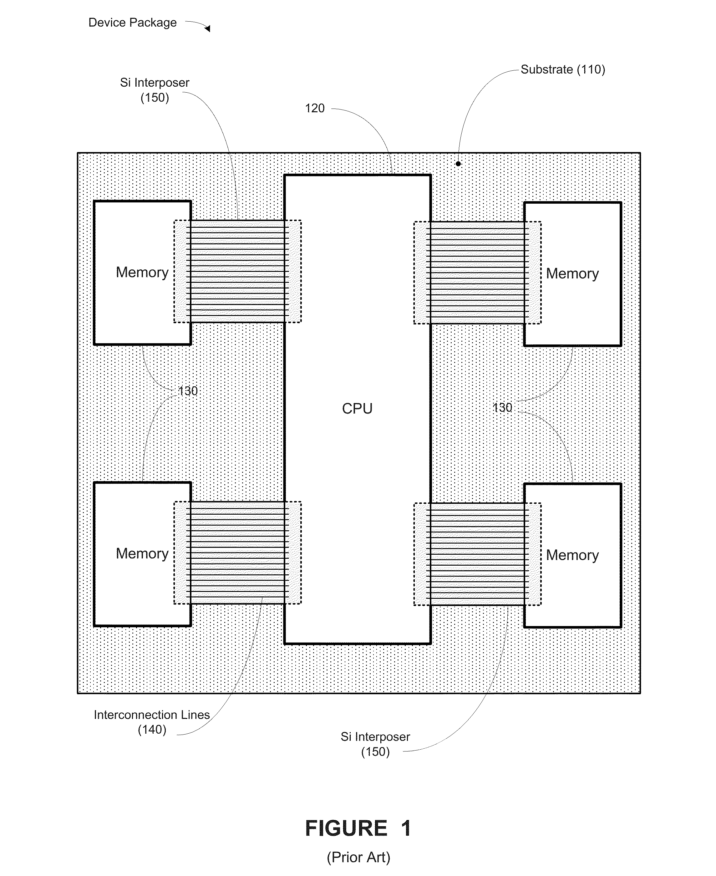
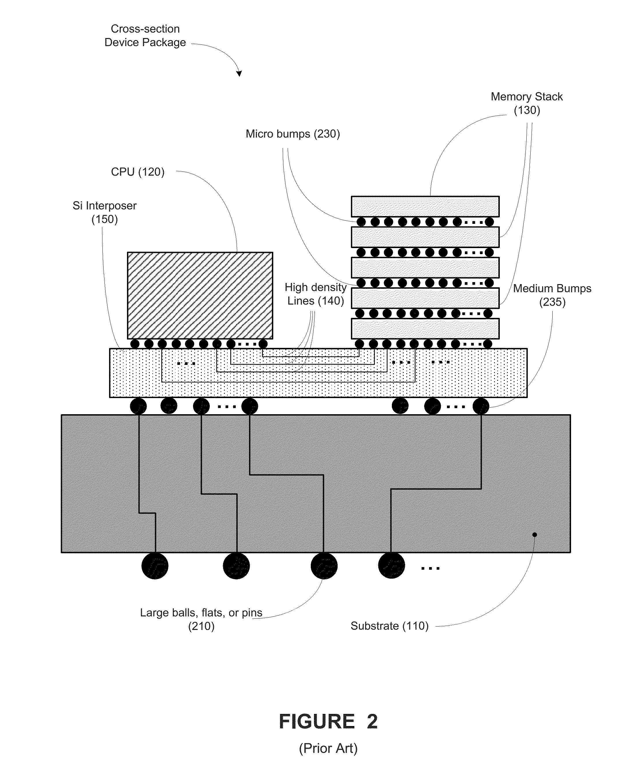
One of the problems associated with the prior art is that the fabrication of the silicon interposer 150 has limitations based upon the reticles used in the processes, e.g., photolithography processes.
This may limit the size of the processor and the memory devices that may be formed in the device package.
However, due to the limitations of the silicon interposer 130, it is increasingly difficult to place larger processors and more than two memory stacks on a single silicon interposer 130.
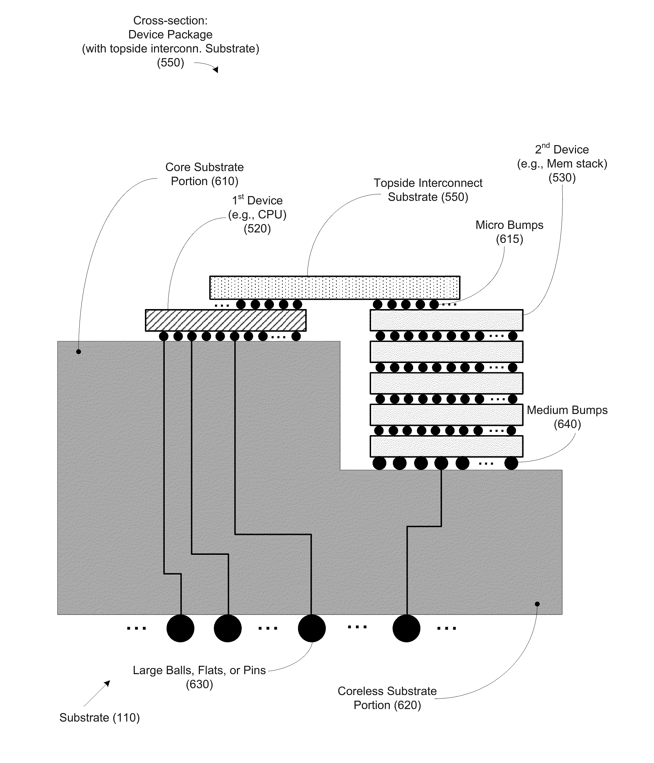
Further, the solution of FIGS. 3 and 4 includes the problem of accommodating varying die heights between the devices on the device package.
This poses a problem as to positioning multiple devices and providing their interconnection via the silicon bridge.
The bottom-oriented silicon bridge below is directed to having the same height for the devices placed in the device package, which can be difficult to accomplish.
Also, accurately aligning the micro bumps and the connections between the devices 120, 130 and the silicon bridge 310 is also a difficult process, which may cause inefficiencies and errors in process multi-device integrated circuit chips.

Method used


Image

  • Top-side interconnection substrate for die-to-die interconnection
  • Top-side interconnection substrate for die-to-die interconnection
  • Top-side interconnection substrate for die-to-die interconnection

Examples


Embodiment Construction

[0029]Various illustrative embodiments of the invention are described below. In the interest of clarity, not all features of an actual implementation are described in this specification. It will of course be appreciated that in the development of any such actual embodiment, numerous implementation-specific decisions must be made to achieve the developers' specific goals, such as compliance with system-related and business-related constraints, which will vary from one implementation to another. Moreover, it will be appreciated that such a development effort might be complex and time-consuming, but would nevertheless be a routine undertaking for those of ordinary skill in the art having the benefit of this disclosure.

[0030]The present subject matter will now be described with reference to the attached figures. Various structures, systems and devices are schematically depicted in the drawings for purposes of explanation only and so as to not obscure the present disclosure with details ...


PUM


Abstract

At least one method, apparatus and system disclosed involves a multi-die integrated circuit device. A first substrate portion having a first height is formed. A first device over the first substrate portion is formed. A second substrate portion having a second height is formed. A second device is formed over the second substrate portion. An interconnect substrate feature is formed above the first and second devices. The interconnect substrate is configured to accommodate a plurality of interconnect lines electrically coupling the first and second devices.

Description

BACKGROUND OF THE INVENTION[0001]1. Field of the Invention[0002]Generally, the present disclosure relates to the manufacture of sophisticated semiconductor devices, and, more specifically, to various methods and structures providing a top-side interconnection substrate for die-to-die interconnection in an integrated circuit chip.[0003]2. Description of the Related Art[0004]The technology explosion in the manufacturing industry has resulted in many new and innovative manufacturing processes. Today's manufacturing processes, particularly semiconductor manufacturing processes, call for a large number of important steps. These process steps are usually vital, and therefore, require a number of inputs that are generally fine-tuned to maintain proper manufacturing control.[0005]The manufacture of semiconductor devices requires a number of discrete process steps to create a packaged semiconductor device from raw semiconductor material. The various processes, from the initial growth of the ...

Claims


Application Information

Patent Timeline
Patent Type & Authority Applications(United States)
IPC IPC(8): H01L25/18H01L21/48H01L25/065H01L23/538H01L25/00H01L23/00
CPCH01L25/18H01L2924/1432H01L24/19H01L24/25H01L24/82H01L25/0657H01L25/0652H01L23/5386H01L21/4853H01L23/5389H01L2225/06513H01L2225/06517H01L2224/24137H01L2224/24226H01L2924/1434H01L25/50H01L21/486H01L23/13H01L23/147H01L23/49811H01L23/5384H01L23/5385H01L24/16H01L24/17H01L2224/16145H01L2224/16227H01L2224/16235H01L2224/17181H01L2924/15159H01L2924/15192H01L2924/15311
Inventor MAK, TAK MING
Owner GLOBALFOUNDRIES INC
Why Eureka
Try Eureka