Root Crop Harvesting Machine

a harvesting machine and root crop technology, applied in the field of root crop harvesting machines, can solve the problems of crop loss and other problems, and achieve the effect of ensuring the maximum conveying, cleaning, and throughput performance of the system, and minimal expenditur

Active Publication Date: 2016-04-28
GRIMME LANDMASCHFAB
View PDF2 Cites 12 Cited by
  • Summary
  • Abstract
  • Description
  • Claims
  • Application Information

AI Technical Summary

Benefits of technology

[0014]It has been found that in particular for potato harvesters of self-propelled configuration that defines a conceivable maximum receiving width, here corresponding to a travel width of 3 m, the concept with the “moveable” deflection conveying unit can be optimally integrated into the machine frame. In this context, by effectively adjustable guides in the area of a coarse haulm belt and of a crop belt downstream of the lifting process, a further transfer of the conveyed material on a sorting stretch that requires only minimal space can be defined such that, for an overall reducible machine length, a quality separation of admixtures from the crop is possible.
[0016]It is understood that the lifting device which is upstream of the cleaning and sorting stretch can be designed preferably with a receiving width that corresponds substantially to the travel width of the machine. The combination of the downstream components in the area of the deflection conveying unit provides that, based on already known four-row machines, a construction with “outwardly positioned separating devices” can be constructed.
[0017]In this context, a first conveying stretch of a comparatively simple design with ascending conveying run is joined in the area of the two separating devices with the deflection conveying unit forming preferably two partial streams. In this way, it is achieved that the conveyed material in the form of root crop, that has been pre-cleaned on the sorting stretch and is supplied in a wide swath by means of at least one screen belt, is optimally distributed in the area of the deflection conveying unit onto the two separating devices each forming a partial stream. Accordingly, even for large-volume conveyed streams a maximum conveying, cleaning, and throughput performance of the system is ensured.
[0018]It has been found that the deflection conveying unit according to the invention enables an optimal separation of the two partial streams of the crop, the crop being moved optimally on the respective partial conveying stretches to the post sorting operation, and the crop, free from admixtures, can be collected or combined downstream of the two partial conveying stretches for unloading.
[0019]In this context, the deflection conveying unit in the area of the upstream ascending conveying stretch is advantageously combined with a two-belt system separating crop and admixtures. With this “double-layer” conveying action, in a comparatively tight space, even respective admixtures that have reached an upper drop zone can be optimally discharged from the sorting system. The belt guiding action is designed in this context such that the deflection conveying unit can be “bypassed” with minimal expenditure and mutual influences of the conveying stretches are avoided in this way.
[0022]A constructive optimization of the component connections that are embodied alternatively as a pivoting, folding and / or push construction in the area of the two lateral separation devices provides that they are each formed as a two-part system in the area of the angled or edge-parallel conveying sections. With these partial component groups that are interacting functionally in the working position with each other, a structure is provided with which handling upon movement into the position of non-use is improved by means of the weight that is adaptable to the actuating possibilities as well as by means of the divided size.

Problems solved by technology

This affects at the same time handling of the system that is to be steered along the contour of the field because performing a complete lifting process in particular near the respective edge zones of the field, may be affected by projecting components of the machine and crop loss can thus occur.

Method used


Image

  • Root Crop Harvesting Machine
  • Root Crop Harvesting Machine
  • Root Crop Harvesting Machine

Examples


Embodiment Construction

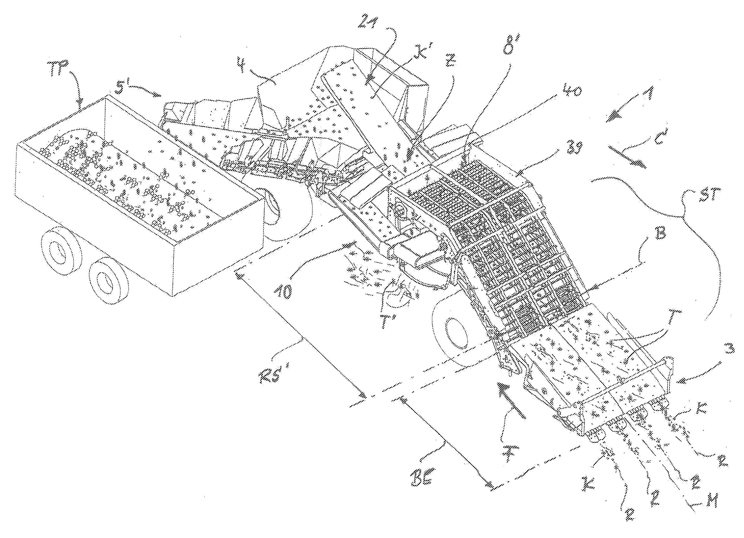
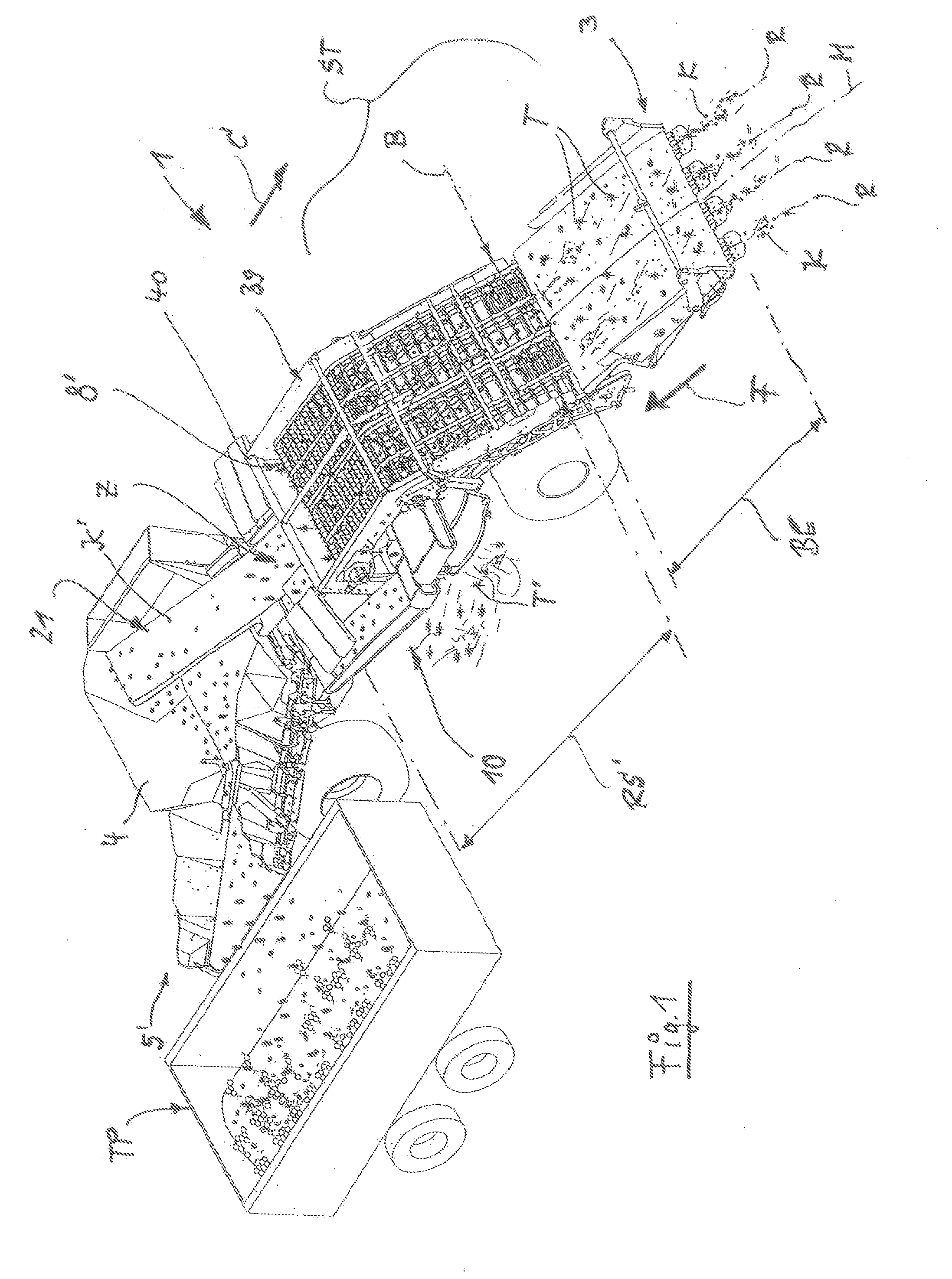
[0054]In FIG. 1 and FIG. 16 in respective basic illustrations the important components of a root crop harvesting machine 1 are illustrated. In this context, when looking also at FIG. 13 to FIG. 15, a principal action and sorting sequence of this “self-propelled” machine 1 in particular when harvesting root crop K from four rows R or potato ridges is apparent. Conceivable is also that the machine 1 to be described in the following in more detail is embodied in the form of a pull-behind potato harvester or stationary cleaning device so that the drive components, not shown in detail in FIG. 1 or FIG. 16, such as motors, driver's cabin, and / or collecting bunker are not needed.

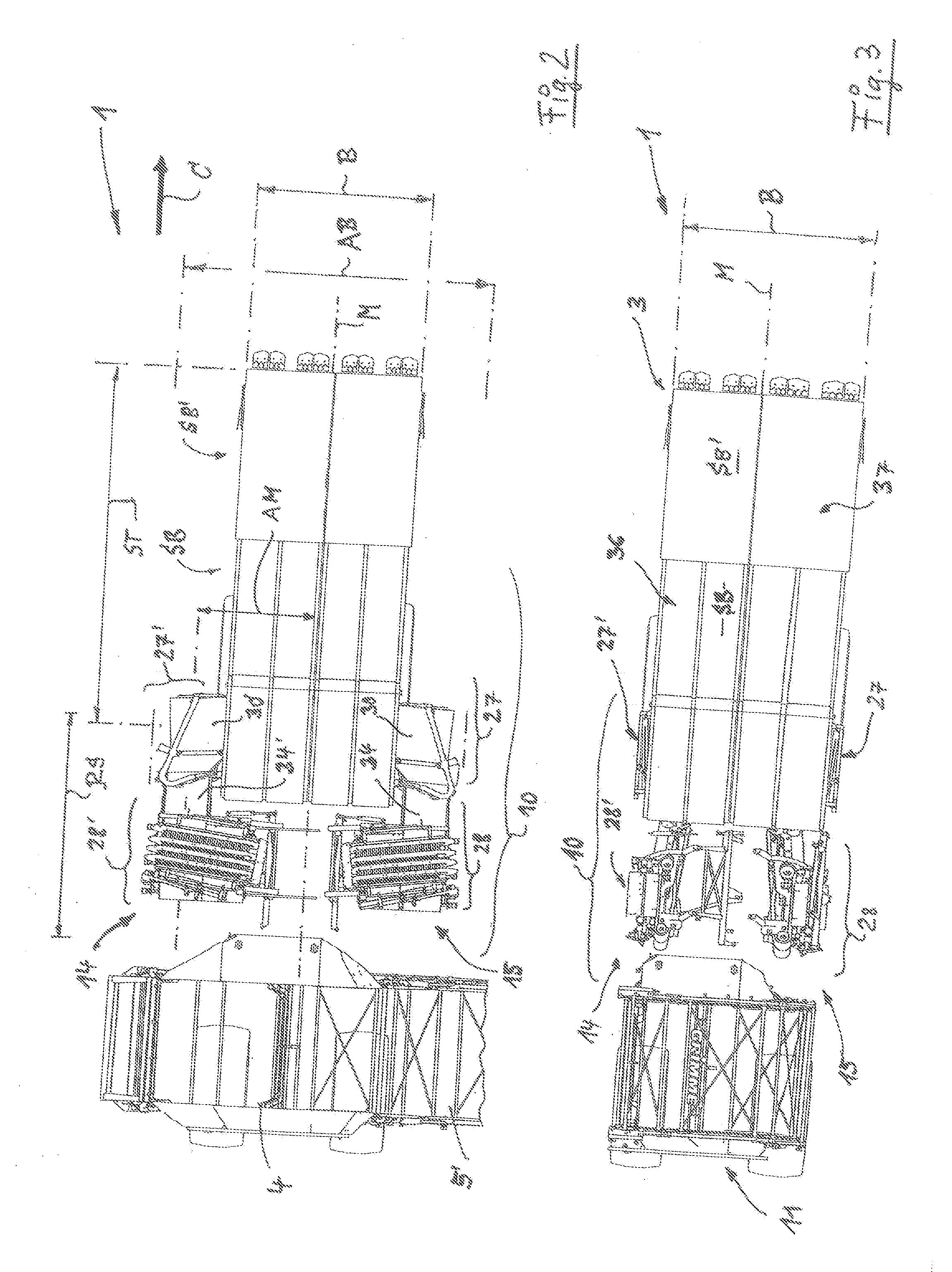
[0055]Such machines 1 have in the leading area of a machine frame 2 (FIG. 16) a lifting device 3. This lifting device 3 has correlated therewith, in conveying direction F downstream thereof, an ascending first sorting stretch ST that is provided with a substantially unchangeable processing width B (FIG. 1). When lo...


PUM


Abstract

A root crop harvesting machine has a crop lifting device that has associated therewith downstream in the conveying direction an ascending first sorting stretch with substantially unchangeable working width. The crop is conveyed across a cleaning stretch to a collecting bunker, wherein a conveying run movable along the ascending sorting stretch is guided to a top drop zone where the conveyed material is transferred onto a downstream conveying stretch. The conveying run in the area of an upper unloading end interacts with at least one deflection conveying unit receiving the conveyed crop stream. This upper deflection conveying unit is provided with at least one separating device that, in working position, is moveable into a position of lateral projecting width so as to project at least on one side past the receiving width of the machine; from this position, it is returnable into a travel position for road travel.

Description

BACKGROUND OF THE INVENTION[0001]The invention concerns a machine for harvesting root crop, in particular in the form of a complete potato harvesting machine embodied as a self-propelled potato harvester or a stationary cleaning machine. Such a machine comprises a lifting device in the forward area of a machine frame, wherein downstream thereof in the conveying direction an ascending first sorting stretch is associated therewith that comprises a substantially unchangeable working width. With the sorting stretch, the admixtures can be sorted out in such a way that the crop in the form of root crop such as beets, potatoes or the like can be conveyed as a respective conveyed material across at least one cleaning stretch to a collecting bunker or an unloading elevator, wherein at least one conveying run movable along the sectionwise ascending sorting stretch is guided at least to a top drop zone and subsequently the respective conveyed material can be transferred onto at least one downs...

Claims


Application Information

Patent Timeline
Patent Type & Authority Applications(United States)
IPC IPC(8): A01D17/00
CPCA01D17/00A01D17/10A01D33/08
Inventor DETTMER, FRANZ-JOSEFBELLERSEN, WERNER
Owner GRIMME LANDMASCHFAB
Why Eureka
Try Eureka