Bale Wrapping Mechanism

a baler and bale technology, applied in the field of baler wrapping mechanism, can solve the problems of twine not spreading out, difficult to keep twine on the edge of the baler, and difficult to maintain the baler edge, etc., and achieve the effect of convenient control, efficient design and optimal delivery

Active Publication Date: 2016-04-28
BLUE LEAF I P INC +1
View PDF9 Cites 15 Cited by
  • Summary
  • Abstract
  • Description
  • Claims
  • Application Information

AI Technical Summary

Benefits of technology

[0008]By aligning the rotation point of the duckbill (the first hinge axis) with a guiding roll, pivoting the duckbill around the rotation point does not influence the tension on the wrapping material. When the duckbill is pivoted, because the wrapping material is guided over the guiding roll that coincides with the hinge point, the length of wrapping material between roll holding station and duckbill remains constant, although the distance between the duckbill and the roll holding station might change. As a result, pivoting the duckbill does not result in the duckbill pulling wrapping material out of the roll holding station or pushing back wrapping material to the roll holding station. Since no pulling or pushing back of wrapping material occurs when pivoting the duckbill, the tension is not significantly influenced by the pivoting of the duckbill, contrary to prior art systems. This allows the tension to be controlled more easily.
[0016]Preferably, the guiding rolls extend substantially parallel to the roll of wrapping material. This allows an easy guidance of the wrapping material over the guiding rolls to the duckbill.

Problems solved by technology

It is desirable for bales to maintain a cylindrical shape, however this has been especially difficult near the edge of the cylindrical bale.
It is difficult for twine to remain on the edge of the bale as well as mechanically placing the twine in that position.
A tension that is too small will typically result in the net not spreading out, but remaining bundled in the centre of the bale.
As a result, when it takes a long time to achieve the optimal tension, a significant amount of net is wrapped in a bundle around the centre of the bale thereby inefficiently using the net material.
That way, no supply of net will be possible and the feeding of net towards the formed bale will not occur.

Method used


Image

  • Bale Wrapping Mechanism
  • Bale Wrapping Mechanism
  • Bale Wrapping Mechanism

Examples


Embodiment Construction

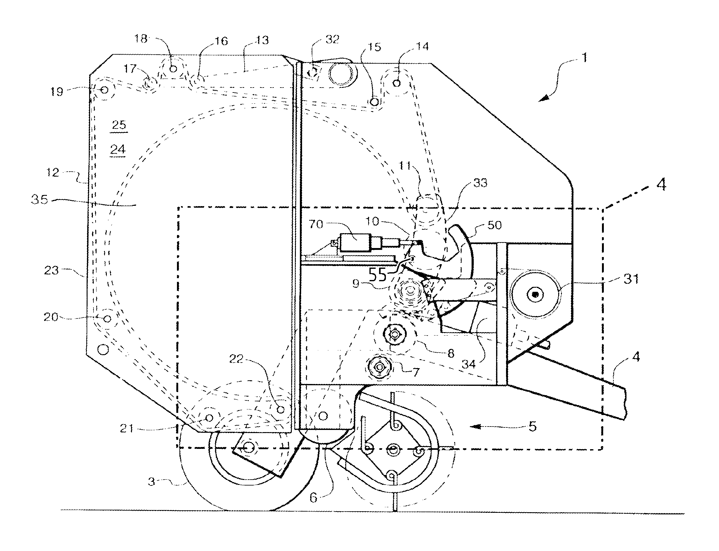
[0023]Referring to the drawings, it is possible to observe the major elements and general operation of the present invention. Left and right references are used as a matter of convenience and are determined by standing at the rear of the round baler and facing the forward end in the normal direction of travel. Likewise, forward and rearward are determined by normal direction of travel of the tractor or round baler. Upward or downward orientations are relative to the ground or operating surface. Horizontal or vertical planes are also relative to ground.

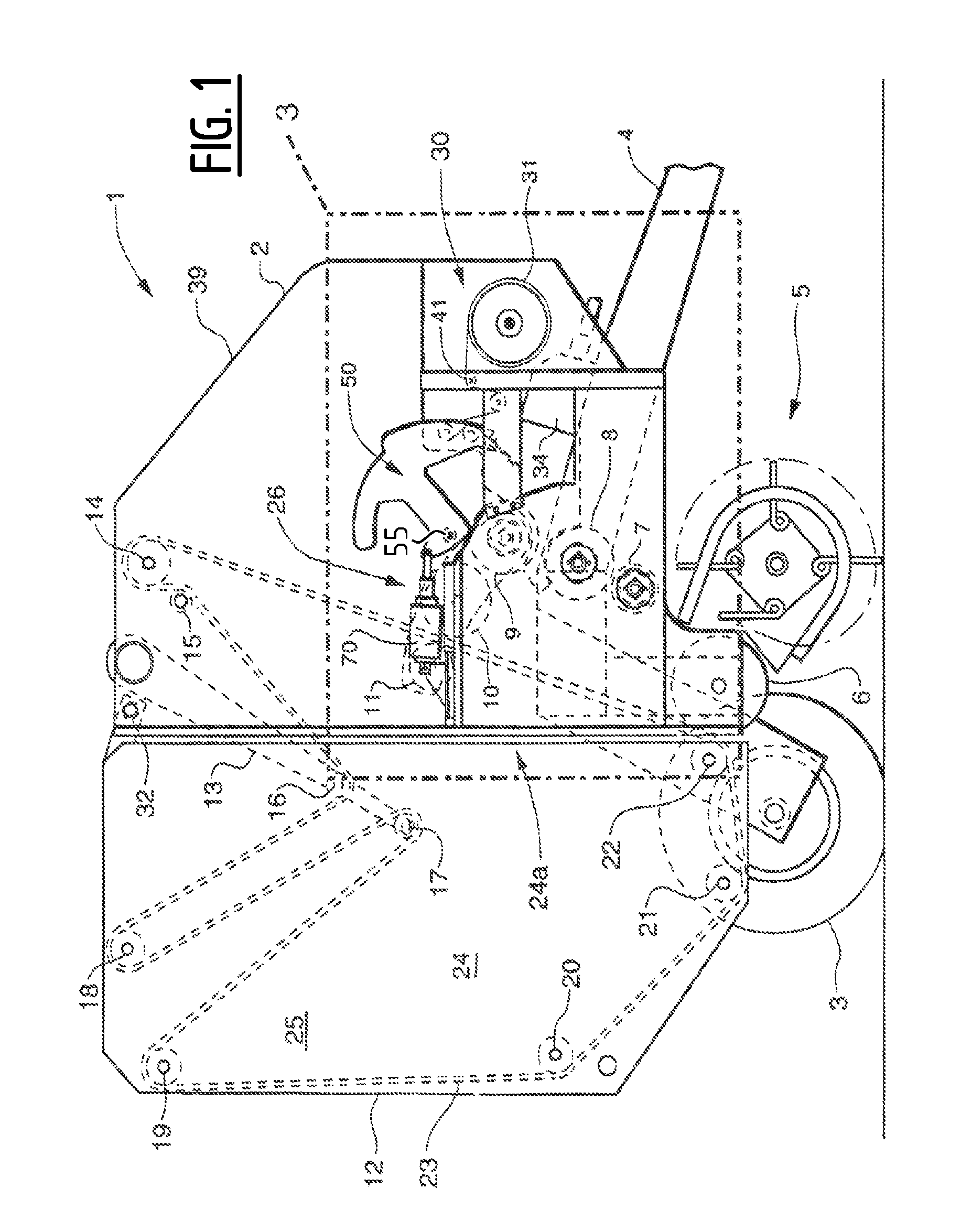
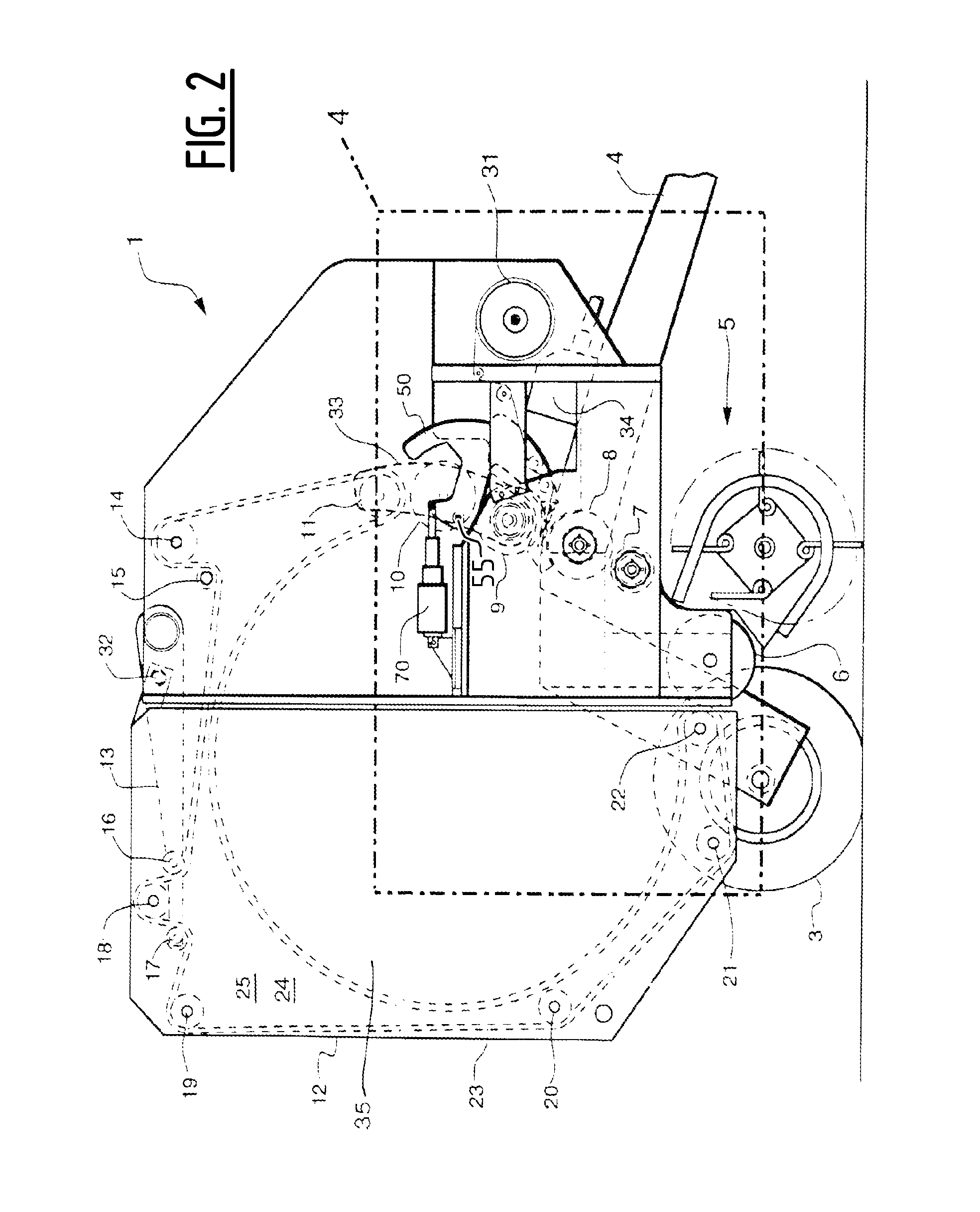
[0024]FIG. 1 illustrates a conventional round baler 1 with the baling chamber 24a ready to receive crop material. The round baler 1 is attached to a tractor (not shown) by means of a tongue 4. Rotational power from the tractor's power-take-off shaft (not shown) is transmitted to a gearbox 34 via a drive shaft. This is the source of power to operate the round baler. It is also possible that a hydraulic motor and pump arrangement may be ...


PUM

PropertyMeasurementUnit
distanceaaaaaaaaaa
external forcesaaaaaaaaaa
tensionaaaaaaaaaa

Abstract

A bale wrapping mechanism has a roll holding station and a duckbill provided for clamping one end of the roll of wrapping material, said duckbill being pivotally mounted, via at least a first hinge, to the baling chamber sidewalls, for delivering said wrapping material to said baling chamber by insertion of said duckbill between adjacent rolls of said baling chamber, wherein the wrapping mechanism further has at least a first guiding roll for guiding the wrapping material between said roll holding station and said duckbill, wherein said first guiding roll axis substantially coincides with the first hinge axis.

Description

[0001]This application is the US National Stage filing of International Application Serial No. PCT / EP2014 / 060856 filed on May 26, 2014 which claims priority to Belgian Application BE2013 / 0367 filed May 27, 2013, each of which is incorporated herein by reference in its entirety.FIELD OF THE INVENTION[0002]The present invention relates to an agricultural round baler. More specifically it relates to an improvement to the wrap dispensing system that allows a net wrap to be placed around a formed bale.BACKGROUND OF THE INVENTION[0003]Agricultural round balers have been used for several decades to collect and bind crop material so as to facilitate the storage of crop material for later use. Generally, a mower or mower-conditioner cuts the crop and arranges it in a windrow for drying. Later, an agricultural tractor pulls a baler over the windrow to collect the crop material. The baler's windrow pickup gathers the cut and windrowed crop and lifts it into the baling chamber. The baling chamb...

Claims


Application Information

Patent Timeline
Patent Type & Authority Applications(United States)
IPC IPC(8): A01F15/07B65B45/00B65B41/12B65B11/04
CPCA01F15/0715A01F15/07B65B41/12B65B45/00B65B11/04
Inventor ROSSEEL, BRAMLAMMERANT, EDDYZWAENEPOEL, KURTVANDE RYSE, JOHAN A.E.
Owner BLUE LEAF I P INC
Why Eureka
Try Eureka