Production method for welded body and production method for gas sensor

Active Publication Date: 2016-04-28
NGK INSULATORS LTD
View PDF6 Cites 3 Cited by
  • Summary
  • Abstract
  • Description
  • Claims
  • Application Information

AI Technical Summary

Benefits of technology

[0024]In this production method for the gas sensor, since the welded body is produced by the above-described production method for the welded body of the present invention, effects similar to those of the above-described production method, for example, the effect of suppressing formation of a protruding portion on the radial outer side can be obtained. Further, in the step (3), at least the welded portion between the first cylindrical body and the second cylindrical body of the welded body is inserted

Problems solved by technology

If the protruding portion is formed in the welded body, problems sometimes

Method used


Image

  • Production method for welded body and production method for gas sensor
  • Production method for welded body and production method for gas sensor
  • Production method for welded body and production method for gas sensor

Examples


example 1

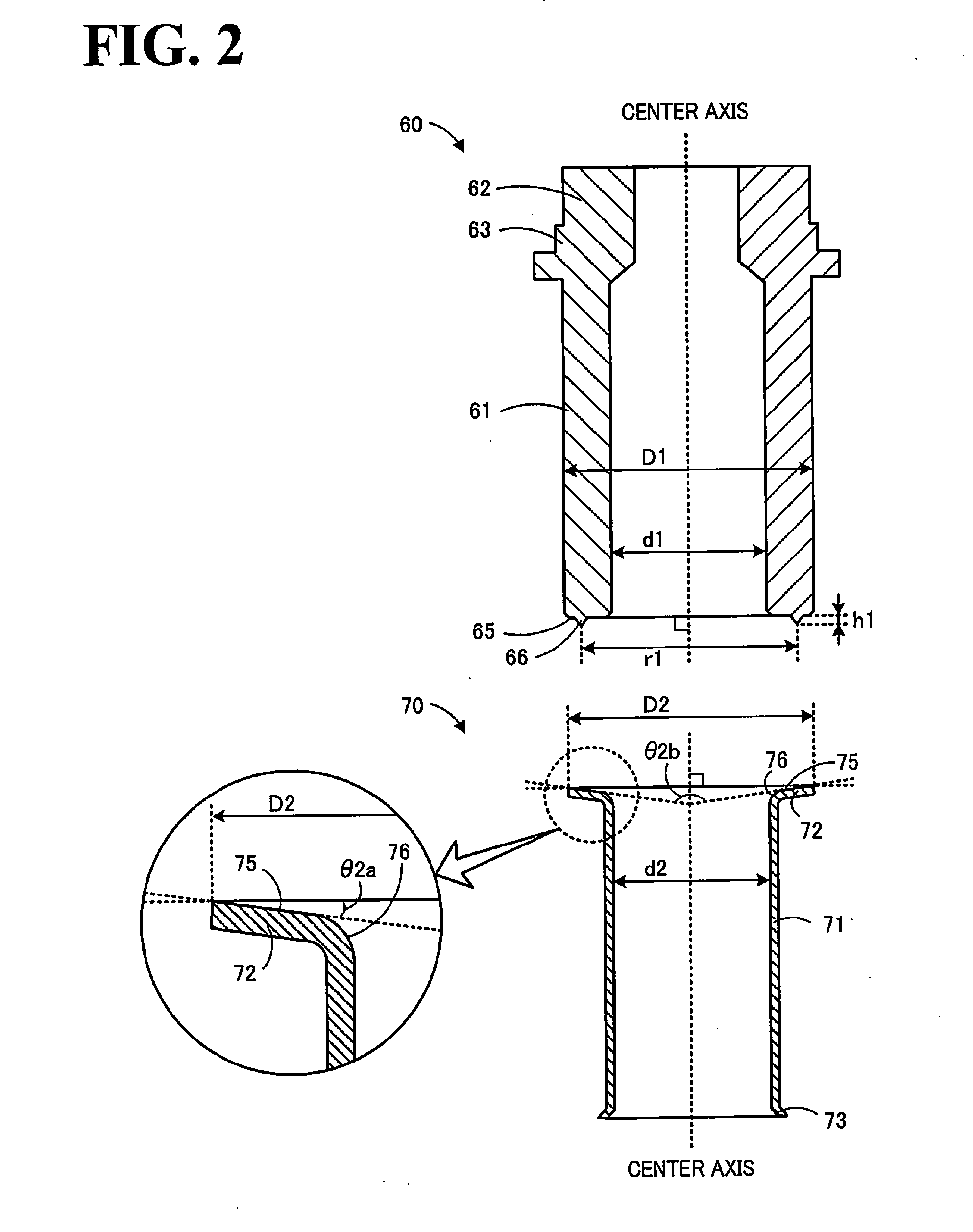
[0076]A main metal piece 60 and an inner cylinder 70 having the shapes illustrated in FIG. 2 were prepared, and a welded body 44 was produced as Example 1 by the above-described production method. The material of the main metal piece 60 and the inner cylinder 70 was SUS 430. The outer diameter D1 and the inner diameter d1 of a body portion 61 of the main metal piece 60 were 14.5 mm and 9 mm, respectively, the diameter r1 of an end (a lower end in FIG. 2) of a projection 66 was 12.5 mm, and the protrusion height h1 of the projection 66 was 0.5 mm. The outer diameter D2 of a second end surface 75 of the inner cylinder 70 was 14 nut, the inner diameter d2 of a body portion 71 was 9 mm, the curvature radius R of a rising portion 76 was 1 mm, the angle θ2a (=angle θc) was 5°, and the angle θ2b was 170°. The thicknesses of the body portion 71, a flange portion 72, and the rising portion 76 were 0.5 mm. Welding conditions were such that the applied voltage was 330 V, the current was 30 kA,...

examples 2 to 5

[0077]Welded bodies 44 were produced as Examples 2 to 5 in a manner similar to that of Example 1 except that the angle θ2a (=angle θc) and the angle θ2b were variously changed. Specifically, in Example 2, the angle θ2a (=angle θc) was 7.5°, the angle θ2b was 165°, and the outer diameter D2 was 14.0 mm. In Example 3, the angle θ2a (=angle θc) was 10°, the angle θ2b was 160°, and the outer diameter D2 was 14.03 mm. In Example 4, the angle θ2a (=angle θc) was 12.5°, the angle θ2b was 155°, and the outer diameter D2 was 14.06 mm. In Example 5, the angle θ2a (=angle θc) was 15°, the angle θ2b was 150°, and the outer diameter D2 was 14.09 mm.


PUM

PropertyMeasurementUnit
Angleaaaaaaaaaa
Angleaaaaaaaaaa
Angleaaaaaaaaaa

Abstract

In a main metal piece 60 and an inner cylinder 70 serving as cylindrical bodies before welding, a second end surface 75 is an inclined surface that inclines toward an end portion opposite from the second end surface 75 as the second end surface 75 extends toward the center axis, and an angle θ2a is 5° to 15°. Thus, the distance between a first end surface 65 and the second end surface 75 positioned in resistance welding increases toward the center axis, and an angle θc (=angle θ2a) between the first end surface 65 and the second end surface 75 is 5° to 15°.

Description

BACKGROUND OF THE INVENTION[0001]1. Field of the Invention[0002]The present invention relates to a production method for a welded body and a production method for a gas sensor.[0003]2. Description of the Related Art[0004]As a method for welding two members, there has hitherto been known resistance welding in which metallic members are brought into contact with each other, are clamped, and are welded by current that flows through contact surfaces thereof by pressurization and energization. For example, PTL 1 describes that two cylindrical members are coaxially resistance-welded with their end portions being in contact with each other.CITATION LISTPatent Literature[0005]PTL 1: JP 2012-210637 ASUMMARY OF THE INVENTION[0006]When a welded body is produced by coaxially resistance-welding two cylindrical bodies, a protruding portion is sometimes formed outside outer peripheral surfaces of the two cylindrical bodies by protrusion of a part of metal melted in a joint portion of the cylindric...

Claims


Application Information

Patent Timeline
IPC IPC(8): B23K11/093
CPCB23K11/0935B23K11/14B23K11/34
Inventor MAKINO, MIYOSHIISAKA, KENJI
Owner NGK INSULATORS LTD
Why Eureka
Try Eureka