
Reducing diffraction effects on an ablated surface

a technology of ablation surface and diffraction effect, which is applied in the field of laser ablation process, can solve the problems of objectionable diffraction patterns produced by laser ablated surfaces to individuals observing the laser ablated surfaces, and unwanted or unintended artifacts

Active Publication Date: 2016-04-28
GENTEX CORP
View PDF3 Cites 19 Cited by
  • Summary
  • Abstract
  • Description
  • Claims
  • Application Information

AI Technical Summary

Benefits of technology

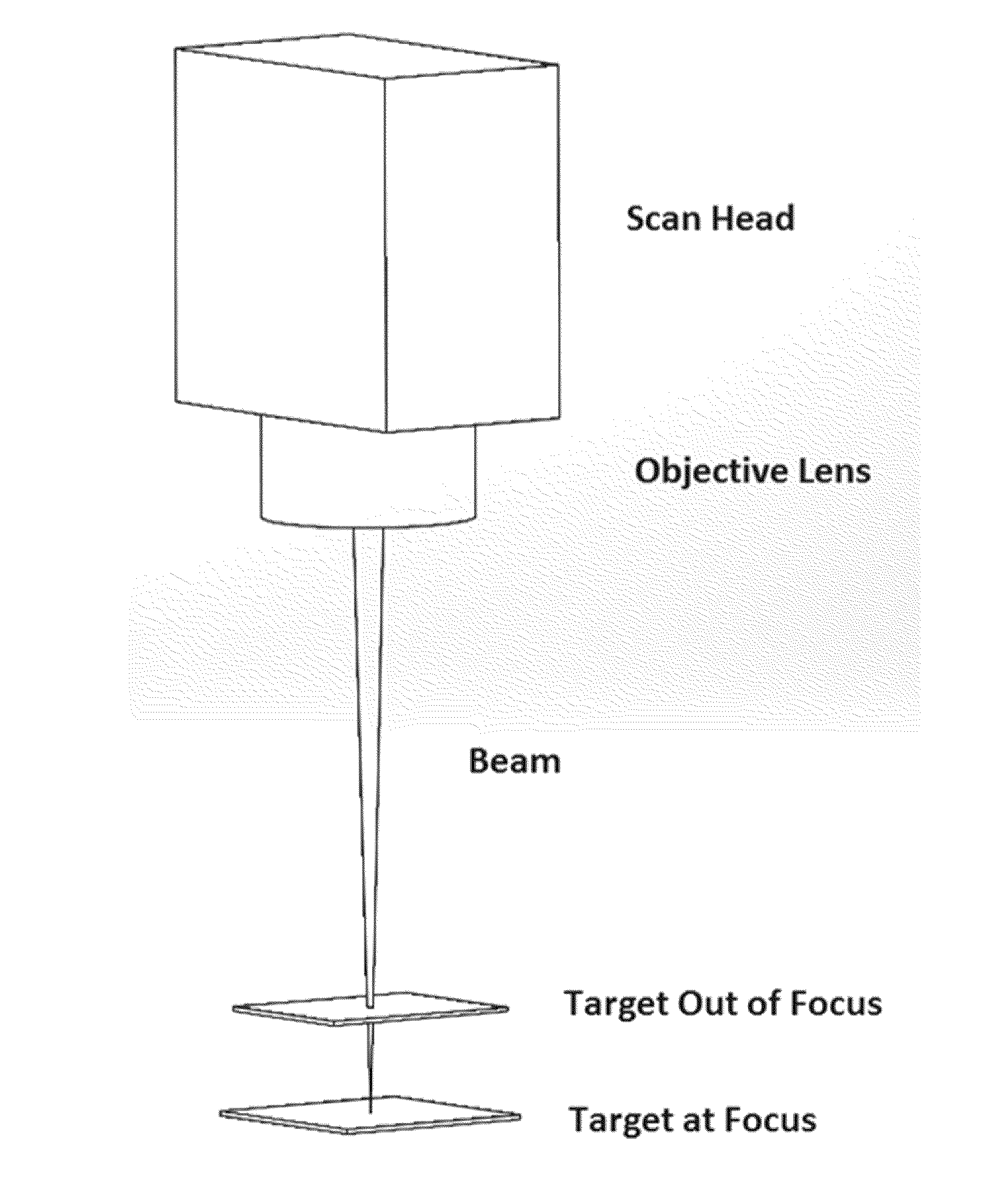
This patent is about a method of removing material from a surface using a laser. The laser is passed through a lens and impinged onto the material. The distance between the lens and the material is varied, and the laser may pass through the surface before impinging on the material. The method can remove material without creating a diffraction effect on the surface, and the removed material can show a periodic structure. The patent also describes an electrochromic assembly produced using this method. The technical effect is a more precise and efficient way to remove material from surfaces using a laser.

Problems solved by technology

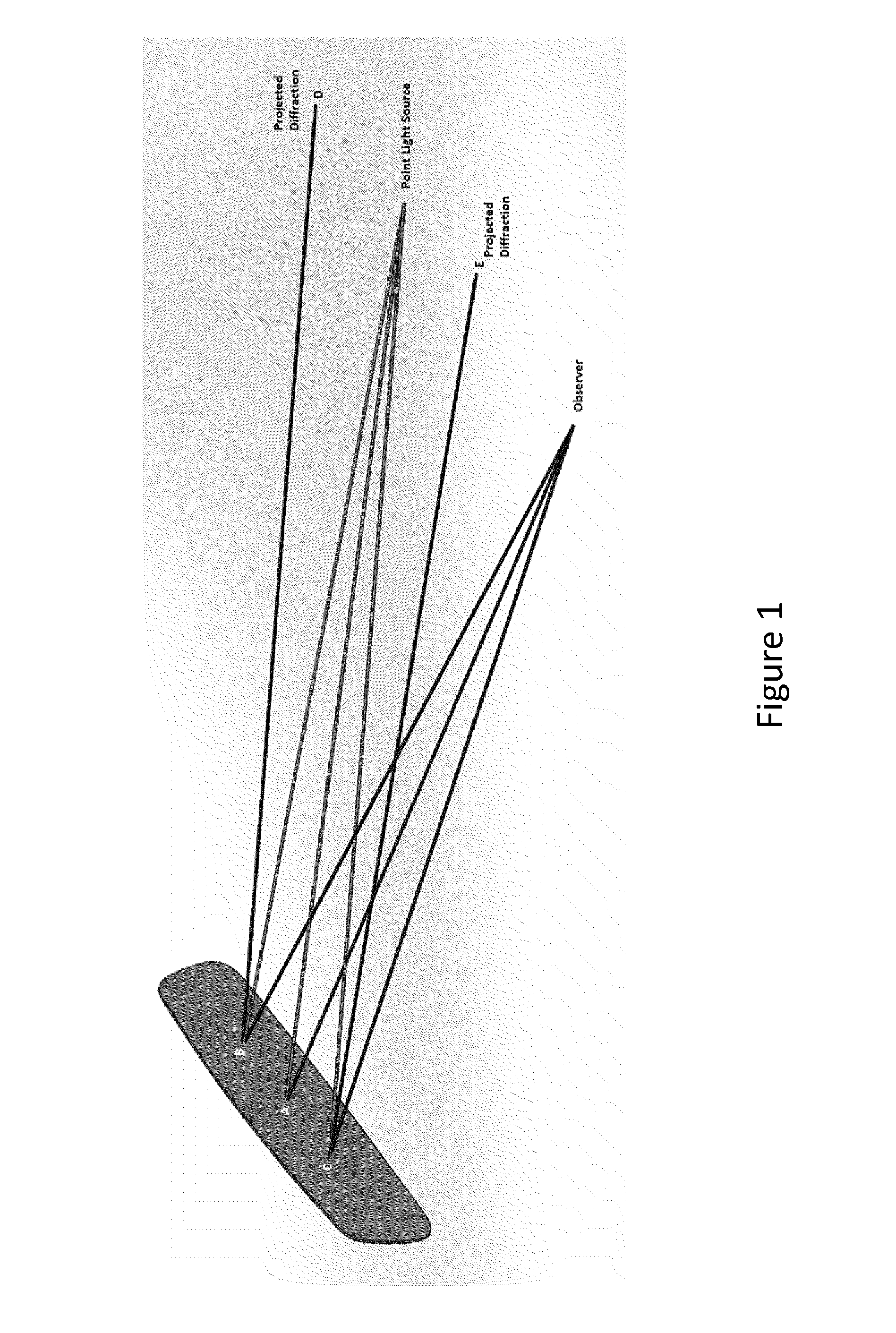
Diffraction patterns that are produced by the diffraction grating can be an unwanted or unintended artifact of the ablation process.
Diffraction patterns produced by laser ablated surfaces may be objectionable to individuals observing the laser ablated surfaces.

Method used


Image

  • Reducing diffraction effects on an ablated surface
  • Reducing diffraction effects on an ablated surface
  • Reducing diffraction effects on an ablated surface

Examples


Embodiment Construction

[0031]Various embodiments are described hereinafter. It should be noted that the specific embodiments are not intended as an exhaustive description or as a limitation to the broader aspects discussed herein. One aspect described in conjunction with a particular embodiment is not necessarily limited to that embodiment and can be practiced with any other embodiment(s).

[0032]As used herein, “about” will be understood by persons of ordinary skill in the art and will vary to some extent depending upon the context in which it is used. If there are uses of the term which are not clear to persons of ordinary skill in the art, given the context in which it is used, “about” will mean up to plus or minus 10% of the particular term.

[0033]The use of the terms “a” and “an” and “the” and similar referents in the context of describing the elements (especially in the context of the following claims) are to be construed to cover both the singular and the plural, unless otherwise indicated herein or c...


PUM

PropertyMeasurementUnit
Lengthaaaaaaaaaa
Lengthaaaaaaaaaa
Fractionaaaaaaaaaa

Abstract

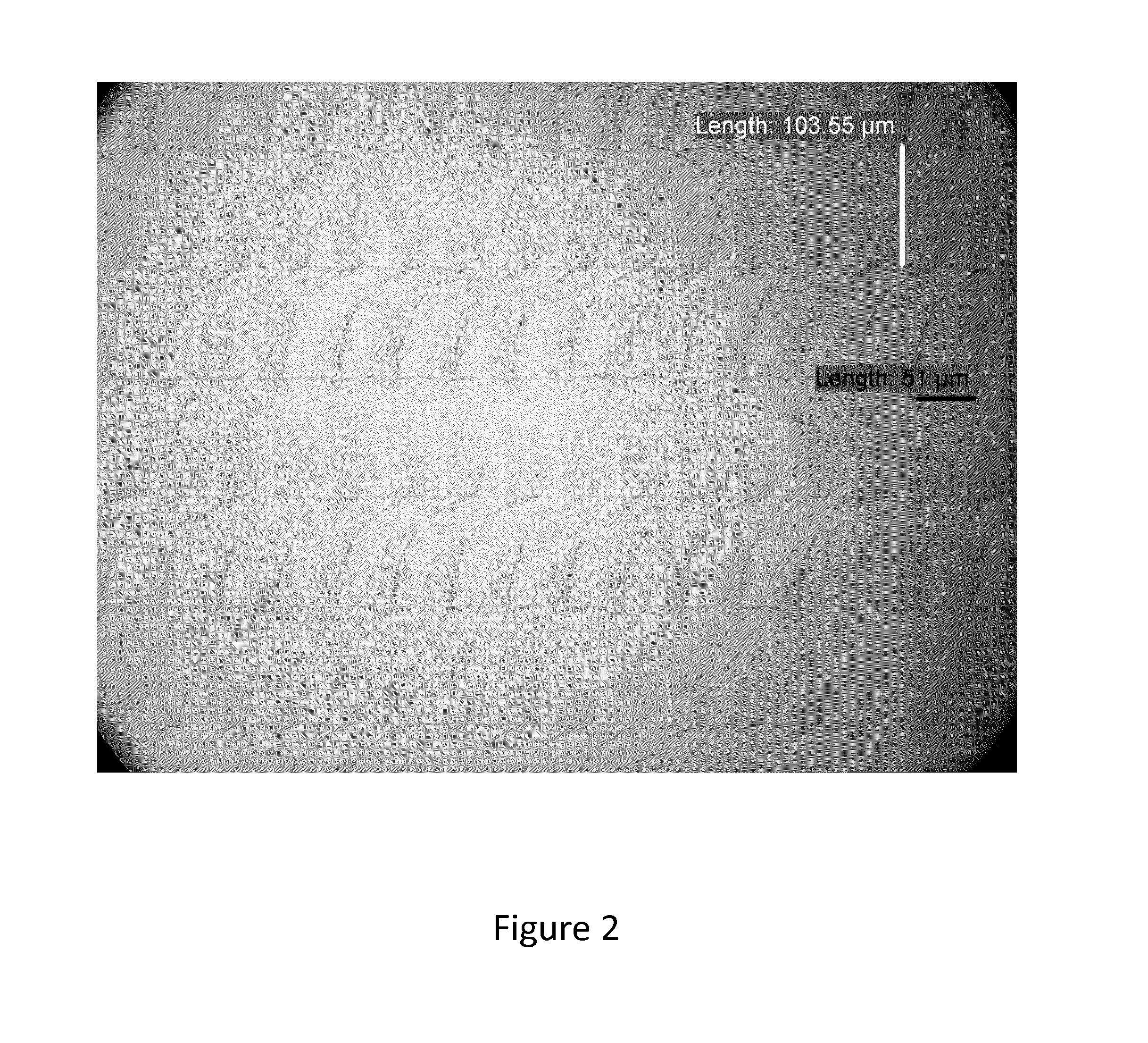
A method is provided for laser ablation that reduces or eliminates a diffraction effect produced by damage to a surface from which an ablated material is removed. The method includes at least one of reducing the amount of surface damage produced and altering the damage structure produced such that it is irregular.

Description

CROSS-REFERENCE TO RELATED PATENT APPLICATIONS[0001]This application claims the benefit of U.S. Provisional Patent Application No. 62 / 068,140, filed on Oct. 24, 2014, the entire disclosure of which is incorporated herein by reference for any and all purposes.TECHNICAL FIELD[0002]The present disclosure generally relates to laser ablation processes and products produced thereby.BACKGROUND[0003]A laser ablation process generally includes selective removal of material at a surface of a workpiece by directing a laser beam at the workpiece. The laser beam is configured to deliver a controlled amount of energy at a laser spot defined where the beam impinges the desired surface. This controlled amount of energy is selected to liquefy, vaporize, or otherwise rapidly expand the surface material at the laser spot to cause it to separate from the workpiece for removal. Laser ablation can be used to remove at least a portion of one or more coatings from a coated substrate.[0004]A conventional la...

Claims


Application Information

Patent Timeline
IPC IPC(8): B29C59/16G02F1/153B23K26/362
CPCB29C59/16G02F1/1533B23K26/362B23K26/048B23K26/361B23K26/57B23K26/355
Inventor LUTEN, HENRY A.BAREMAN, DONALD L.SCOTT, THOMAS J.GEERLINGS, KURTIS L.TONAR, WILLIAM L.OLESEN, NIELS A.
Owner GENTEX CORP
Learn More