Reflecting pyramid wave-front sensor

A wavefront sensor and pyramid technology, applied in the field of adaptive optics, achieves the effects of high measurement accuracy, easy adjustment and simple structure

Inactive Publication Date: 2009-12-30
INST OF OPTICS & ELECTRONICS - CHINESE ACAD OF SCI
View PDF1 Cites 20 Cited by
  • Summary
  • Abstract
  • Description
  • Claims
  • Application Information

AI Technical Summary

Problems solved by technology

[0005] The technical problem to be solved by the present invention is to provide a wavefront sensor with high detection accuracy, wide operating spectrum, simple structure, low adjustment difficulty, and can meet the needs of small and micro self-adaptive sensors in view of the technical deficiencies of existing wavefront sensors using pyramids for wavefront measurement. Reflective Pyramid Wavefront Sensors Required by Optical Systems

Method used


Image

  • Reflecting pyramid wave-front sensor
  • Reflecting pyramid wave-front sensor
  • Reflecting pyramid wave-front sensor

Examples


Embodiment Construction

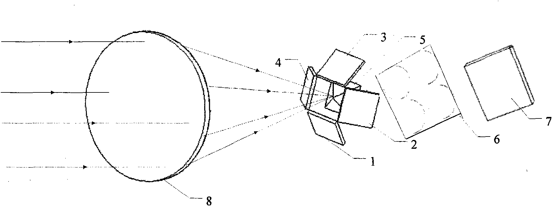
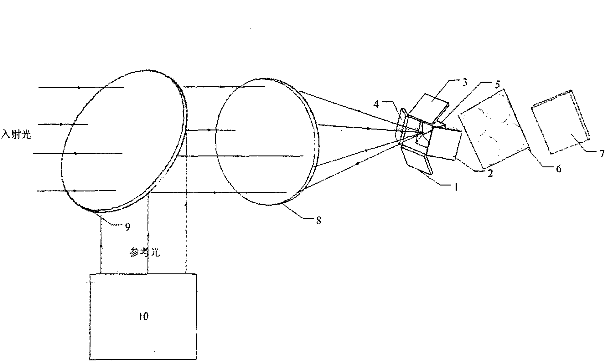
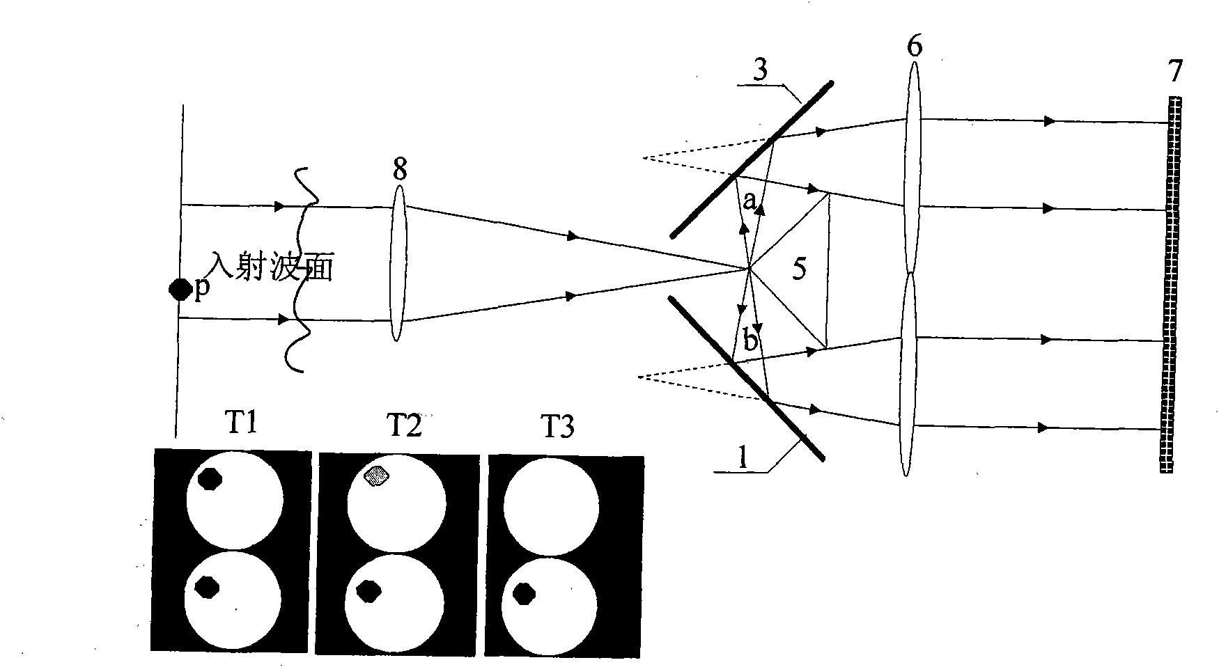
[0022] Such as figure 1 As shown, the technical solution of the present invention specifically includes a first mirror 1, a second mirror 2, a third mirror 3, a fourth mirror 4, a reflection pyramid 5, a 2×2 microlens array 6, a photodetector 7. Focusing lens 8. 2×2 microlens array 6 is placed between reflective pyramid 5 and photodetector 7; first reflector 1, second reflector 2, third reflector 3 and fourth reflector 4 respectively Be positioned at the outside of four facets of reflecting pyramid 5, the mirror surface of four reflecting mirrors and the included angle of bottom surface equal to the base included angle of reflecting pyramid 5, and four reflecting mirrors are parallel with the facing of reflecting pyramid 5; Described reflecting pyramid The pyramid apex of 5 is positioned at the focal plane position of focusing lens (8), and four facets of reflective pyramid 5 are reflective surfaces, and the light beam that passes through focusing lens 8 is focused on the apex...


PUM


Abstract

The invention relates to a reflecting pyramid wave-front sensor. Four reflecting mirrors and reflecting pyramids are matched for carrying out splitting reflecting on incident light; 2*2 micro-lenses arrays carry out relay imaging on reflecting sub light beam; four sub pupil images are formed on the four quadrants of a photo detector; wave-front slop information is calculated according to the light intensity distribution difference of the four sub pupil images; and wave front distortion phase distribution is further reconstructed. The reflecting pyramid wave-front sensor has the advantages that the light utilization rate is high, the measurement dynamic range is large, dispersion effect and diffraction effect do not occur, the volume is small, the structure is compact and the adjustment is easy, and the reflecting pyramid wave-front sensor can be applied to the measurement on wave front by an adaptive optical system.

Description

technical field [0001] The invention relates to the field of adaptive optics, in particular to a reflective pyramid wavefront sensor for wavefront quality measurement. Background technique [0002] Adaptive optics uses optoelectronic devices to measure, calculate and correct the wavefront quality of light waves in real time, so that the optical system can automatically adapt to changes in external conditions and always maintain a good working condition. With the development of adaptive optics technology, its application range has gradually expanded from early military applications to industrial and civilian applications, such as inertial confinement fusion (ICF), medical diagnosis of fundus lesions, and optical communications. [0003] Correcting wavefront aberrations in adaptive optics systems requires accurate detection of the quality of incident wavefronts, and wavefront sensors are a key part of the adaptive optics system for accurate measurement of incident wavefront ab...

Claims


Application Information

Patent Timeline
Patent Type & Authority Applications(China)
IPC IPC(8): G01J9/00
Inventor 蔡冬梅杨欢姚军
Owner INST OF OPTICS & ELECTRONICS - CHINESE ACAD OF SCI
Why Eureka
Try Eureka