Tube spreading device and boiler cleaning system

a technology of boiler cleaning and spreading device, which is applied in the direction of mechanical equipment, manufacturing tools, lighting and heating equipment, etc., can solve the problems of reducing the possibility of permanent deformation of the tube, leakage in the pressure boundary, etc., and achieves the effect of improving the safety of individual service personnel, cost-effective use and maintenance, and effective and efficien

Active Publication Date: 2016-04-28
HRST
View PDF13 Cites 6 Cited by
  • Summary
  • Abstract
  • Description
  • Claims
  • Application Information

AI Technical Summary

Benefits of technology

[0010]The boiler cleaning apparatus and method provides for cleaning the exterior surfaces of a heat exchanger. The apparatus and method include tools and steps, respectively, for temporarily spreading tubes and holding open the tubes to form tube lanes. Once access to a lane is attained, a nozzle assembly having an outlet for blowing high velocity cleaning fluid may be selected from a group of nozzle assemblies. The selected nozzle assembly will have an outlet for blowing fluid in a direction that effectively cleans the tubes adjacent the opened lane. After the tubes are cleaned the tool for holding the lane opened is removed and the process is repeated for another lane. Accordingly, the invention presents an apparatus for cleaning boiler tubes that is effective and efficient, while being cost effective to use and maintain, while improving the safety to individual service personnel.
[0011]The tube spreading device in some embodiments penetrates into the vertical or horizontal rows of a tube bank an enhanced depth dimension, and requires less time to accomplish penetration and tube spreading, compared to the known tube spreading devices. The amount of flexure on the vertical tubes of the heat exchanger may be controlled / regulated by using fixed width tube spreading devices. The fixed width tube spreading devices, which are sized dependent on the specifications of each job, in some embodiments minimize the risk of exceeding acceptable stress levels on the flexed tubes. Minimizing risks associated with exceeding acceptable stress levels on the flexed tubes reduces the possibility of permanent deformation of the tubes, or causing leaks in the pressure boundary. The tube spreading device is designed for use with one or two man crews, depending on the site specifics, providing more convenient operation characteristics. The tube spreading device additionally improves safety to individuals by providing holes or points to attach “leashes” in order to minimize drop hazards.
[0012]The tube spreading devices in some embodiments combine the tube spreading and blocking functions to improve the efficiency of cleaning activities.

Problems solved by technology

Minimizing risks associated with exceeding acceptable stress levels on the flexed tubes reduces the possibility of permanent deformation of the tubes, or causing leaks in the pressure boundary.

Method used


Image

  • Tube spreading device and boiler cleaning system
  • Tube spreading device and boiler cleaning system
  • Tube spreading device and boiler cleaning system

Examples


Embodiment Construction

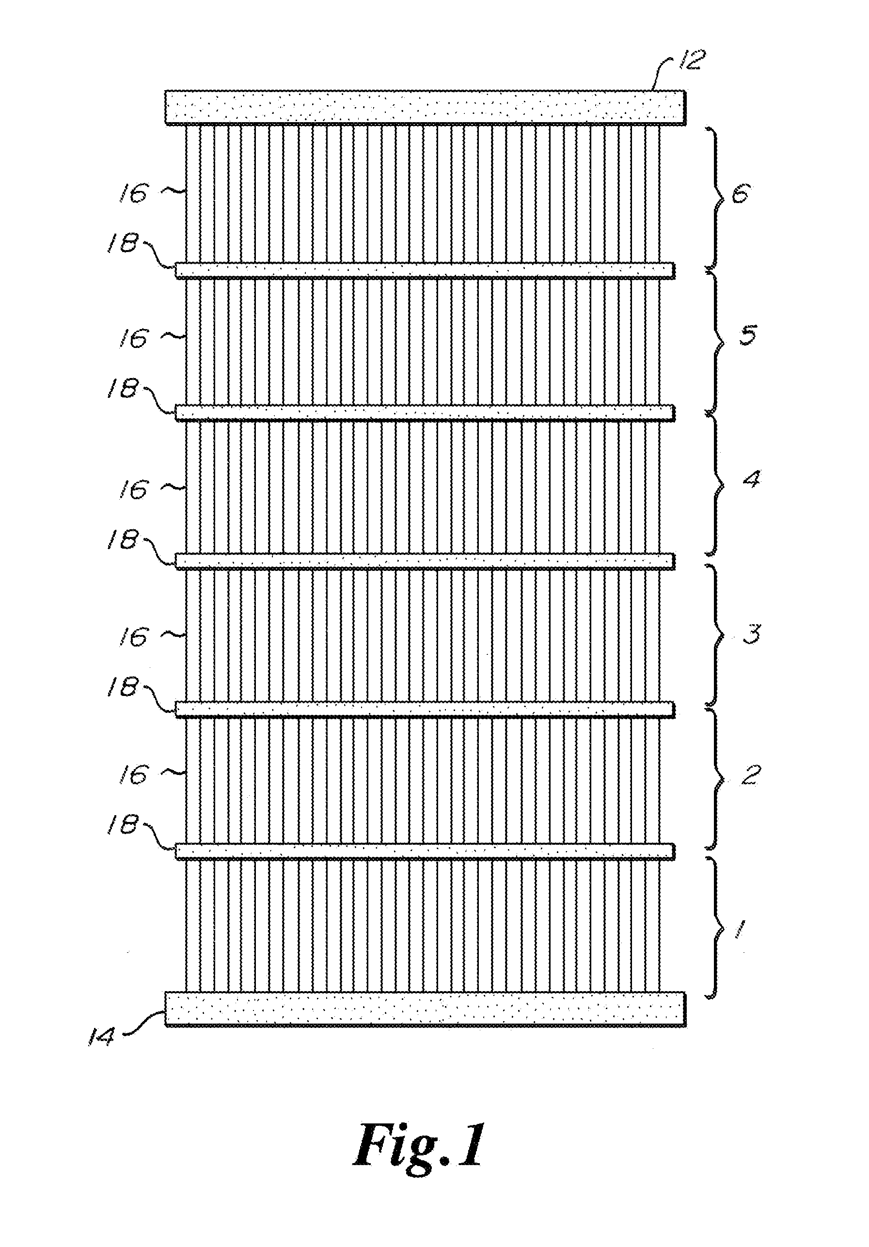
[0031]Attention is first directed to FIG. 1, which illustrates a typical panel commonly found within a heat recovery steam generator or HRSG. The typical panel comprises respective upper and lower headers 12, 14, finned or bare water tubes 16, and tube ties 18. Smaller areas or levels (1-6) between the tube ties are focused on during the cleaning process.

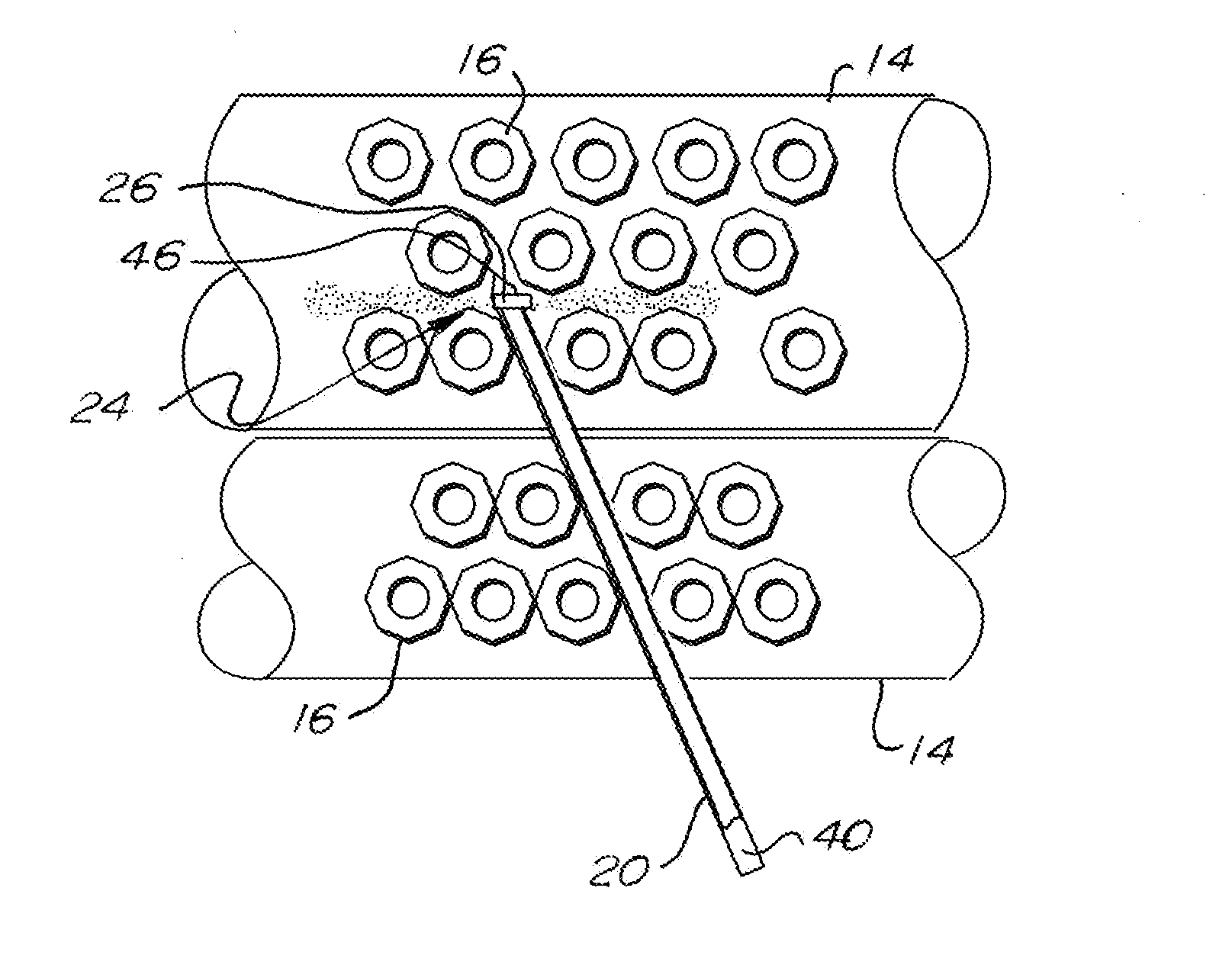
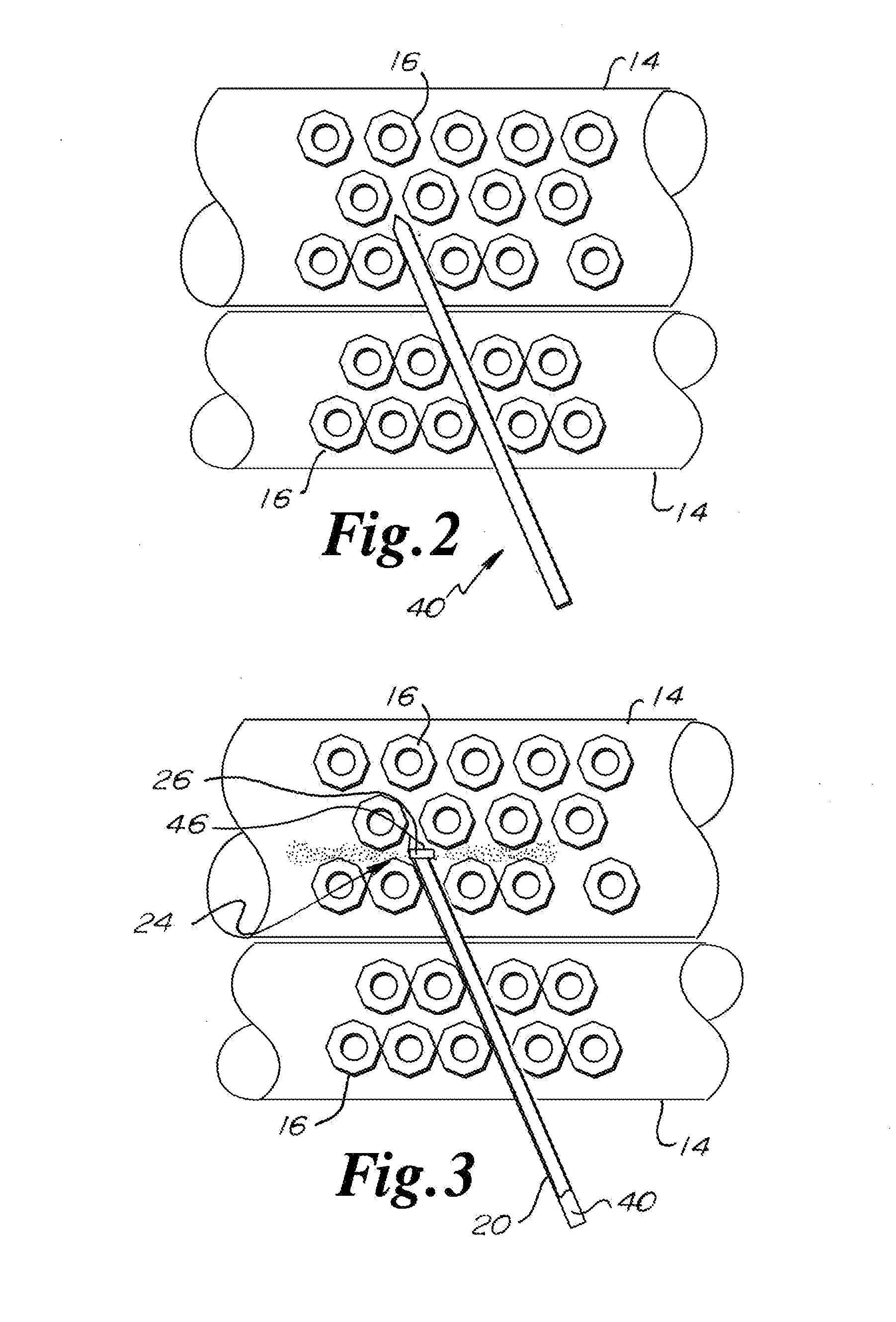
[0032]A side blow nozzle assembly is shown in FIG. 3. Side blow nozzle assembly comprises an elongate nozzle pipe 20 having a cleaning fluid entry end and spraying end 24. A pipe 26 having diametrically opposed openings defines the spraying end 24. Pipe 26 is perpendicular to nozzle pipe 20.

[0033]An angled side blow nozzle assembly may alternatively be utilized which is similar to the nozzle assembly described immediately above, except that the pipe 26 disposed at an acute angle of approximately sixty degrees with nozzle pipe 20. The length of the nozzle pipe and the dimensions of the fluid flow paths and spray outlets in all of the...


PUM


Abstract

The boiler cleaning apparatus and method provides for cleaning the exterior surfaces of a heat exchanger. The apparatus and method include tools and steps, respectively, for temporarily spreading tubes and holding open the tubes to gain access to tube lanes. Once access to a lane is attained, a nozzle assembly having an outlet for blowing high velocity cleaning fluid is selected from a group of nozzle assemblies. The selected nozzle assembly will have an outlet for blowing fluid in a direction that effectively cleans the tubes adjacent the opened lane. After the tubes are cleaned the tool for holding the lane opened is removed and the process is repeated for another lane.

Description

CROSS-REFERENCE TO RELATED APPLICATIONS[0001]This application claims priority to U.S. Provisional Patent Application Ser. No. 62 / 068,171, filed Oct. 24, 2014, entitled Tube Spreading Device which is incorporated herein by reference in its entirety.BACKGROUND OF THE INVENTION[0002]1. Field of the Invention[0003]The present invention generally relates to devices used in the cleaning of heating, ventilation, and air conditioning (HVAC) apparatus, and more specifically, to a boiler cleaning apparatus and method for cleaning the external surfaces of water-tube heat exchangers.[0004]2. Description of the Related Art[0005]The exterior surfaces of heat exchange tubes in a heat recovery steam generator or HRSG are exposed to the byproducts of combusting fuel gases. These byproducts include but are not limited to soot, slag and ash that adhere to the surfaces of the tubes, creating a layer that inhibits the rate of heat transfer between the fluid (water and / or steam) flowing inside the tubes ...

Claims


Application Information

Patent Timeline
Patent Type & Authority Applications(United States)
IPC IPC(8): F22B37/54
CPCF22B37/54F28G1/166F28G15/00B25B9/02
Inventor KROWECH, ROBERT JAMESOLSON, SCOTT DANIEL
Owner HRST
Why Eureka
Try Eureka