Transparent PSTN Failover

a failover platform and transparent technology, applied in data switching networks, frequency-division multiplexes, instruments, etc., can solve the problems of unsatisfactory customer solutions, pstn failover platforms cannot protect customers from 100% of the entire spectrum of outage possibilities, and cost became the driver of network construction

Active Publication Date: 2016-04-28
CENTURYLINK INTPROP
View PDF8 Cites 7 Cited by
  • Summary
  • Abstract
  • Description
  • Claims
  • Application Information

AI Technical Summary

Benefits of technology

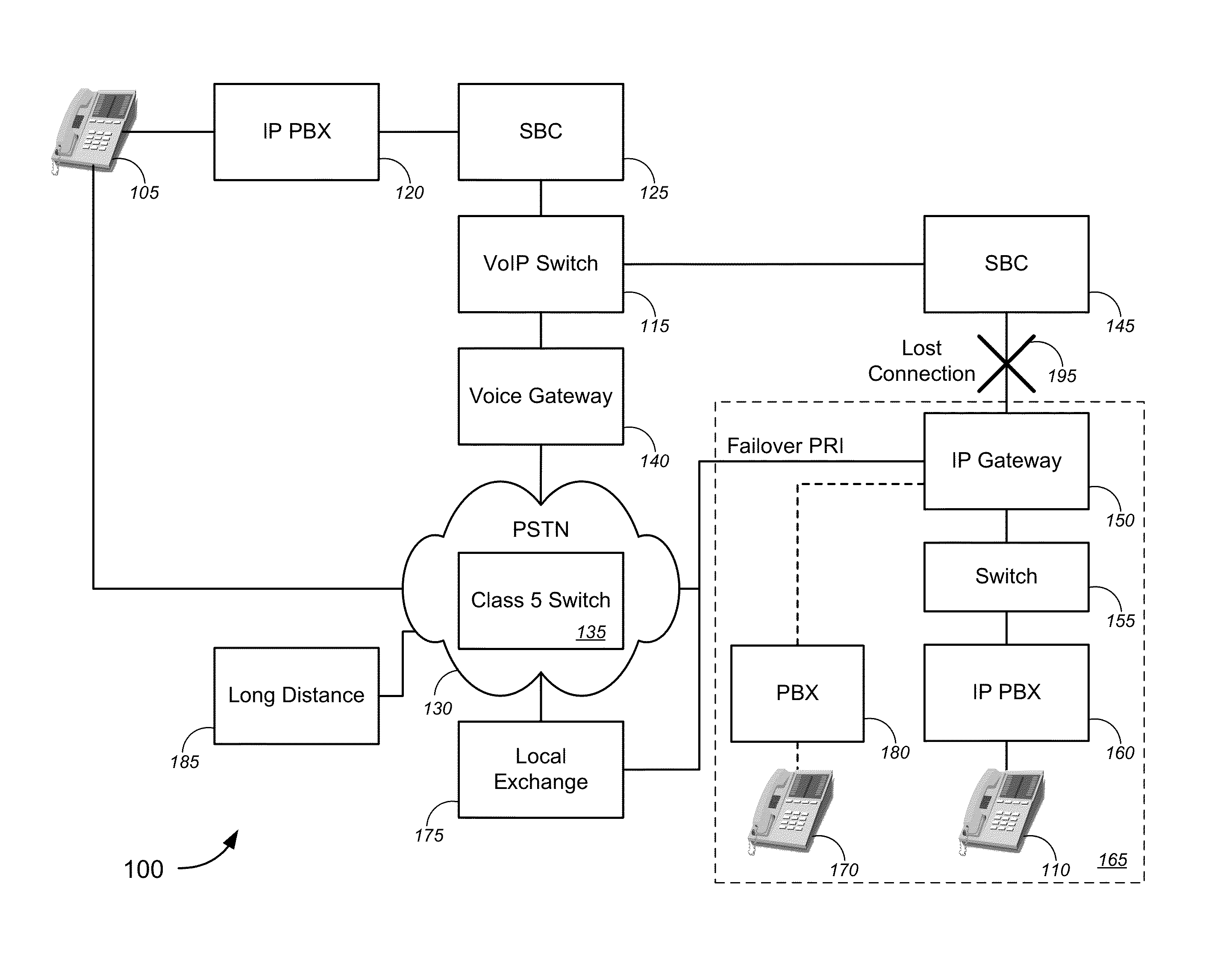
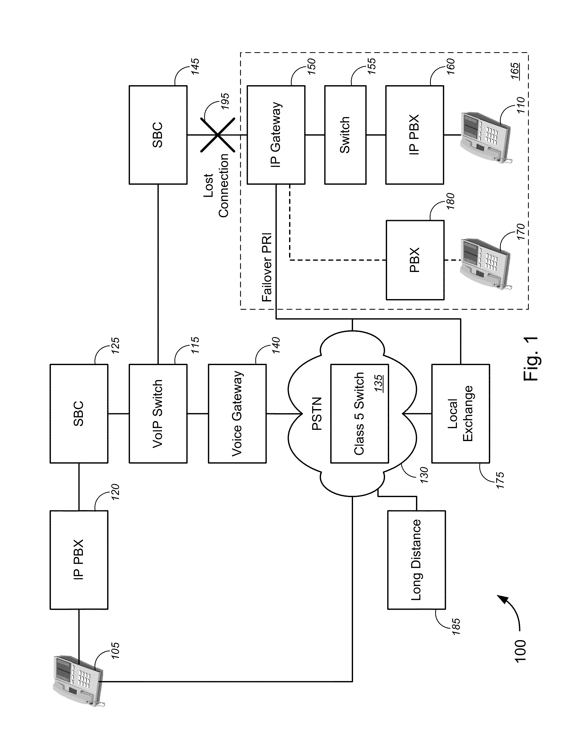
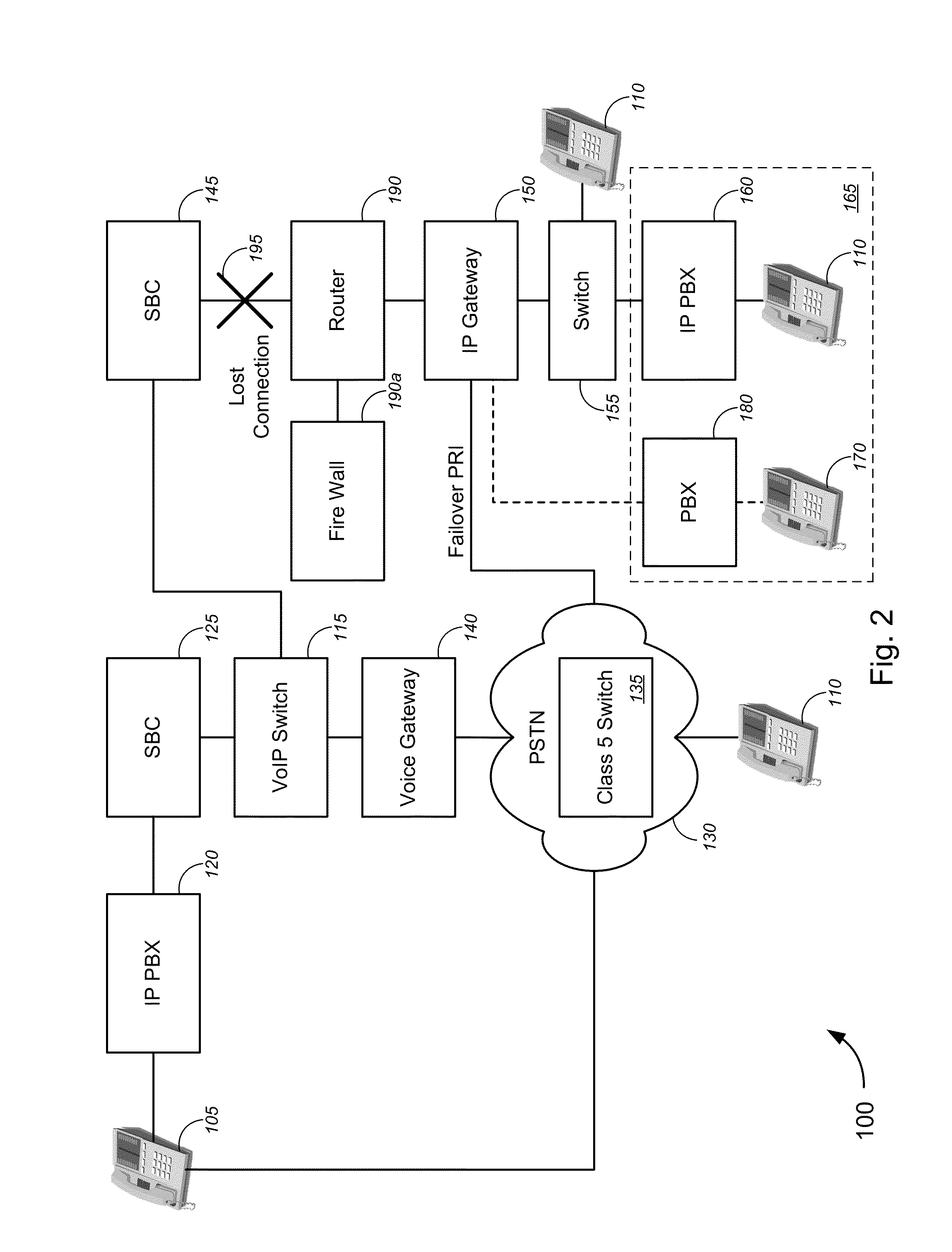
[0010]Either a Class 5 switch at the PSTN or the IP gateway might determine that the redirect number is associated with a PSTN failover, and based on such determination, might replace the redirect number with the original called number in the call request. The IP gateway might then route the call request to the original called party at the original called number via an IP PBX that might terminate (i.e., establish) the call connection between the calling party and the called party, without interception by an operator, a receptionist, or an auto attendant. In so doing, the transparent PSTN failover may be implemented, with none of the calling party, the called party, or the IP PBX being aware that a failover has occurred.

Problems solved by technology

However, in the era of deregulation, data networks were built in a competitive environment and network costs directly impacted customer pricing, so cost became the driver of network construction.
As such, currently implemented PSTN failover platforms cannot protect a customer from 100% of the entire spectrum of outage possibilities that can occur.
However, this is an unsatisfactory customer solution.
For large customers, this limited failover feature may be inadequate because the number of failover calls may overwhelm these customers, and these customers may not be staffed to deal with answering every call and the Auto Attendant programming can be difficult.
Redundant VoIP switches, dual SBCs, or alternate access circuits, and the like might merely address specific instances of potential outages, but do not provide the functionality achievable by the various embodiments described herein.

Method used


Image

  • Transparent PSTN Failover
  • Transparent PSTN Failover
  • Transparent PSTN Failover

Examples


Embodiment Construction

[0026]While various aspects and features of certain embodiments have been summarized above, the following detailed description illustrates a few exemplary embodiments in further detail to enable one of skill in the art to practice such embodiments. The described examples are provided for illustrative purposes and are not intended to limit the scope of the invention.

[0027]In the following description, for the purposes of explanation, numerous specific details are set forth in order to provide a thorough understanding of the described embodiments. It will be apparent to one skilled in the art, however, that other embodiments of the present invention may be practiced without some of these specific details. In other instances, certain structures and devices are shown in block diagram form. Several embodiments are described herein, and while various features are ascribed to different embodiments, it should be appreciated that the features described with respect to one embodiment may be i...


PUM


Abstract

Novel tools and techniques for implementing Transparent PSTN Failover. In some embodiments, a VoIP switch might receive a call request for connection between a calling party at a calling telephone number (“TN”) and a called party at a called TN. Based on a determination that connection via a session border controller (“SBC”) between the VoIP switch and an Internet Protocol (“IP”) gateway has been lost, the VoIP switch might route the call request to a PSTN redirect TN through the PSTN. One of the Class 5 switch of the PSTN or the IP gateway might replace the redirect TN with the called TN, based on a determination that the redirect TN represents a PSTN failover. The IP gateway may then route the call request to an IP PBX for terminating (establishing) the call connection between calling party and called party, without interception by an operator, receptionist, or auto attendant.

Description

CROSS-REFERENCES TO RELATED APPLICATIONS[0001]This application is the continuation of U.S. patent application Ser. No. 13 / 908,644 (the “'644 application”), filed Jun. 3, 2013 by Charles A. Palmer et al. (attorney docket no. 020370-010300US), entitled, “Transparent PSTN Failover,” which claims priority to U.S. Patent Application Ser. No. 61 / 784,677 (the “'677 application”), filed Mar. 14, 2013 by Charles A. Palmer et al. (attorney docket no. 020370-010301US), entitled, “Transparent PSTN Failover,” the entire disclosure of each of which is incorporated herein by reference in its entirety for all purposes.COPYRIGHT STATEMENT[0002]A portion of the disclosure of this patent document contains material that is subject to copyright protection. The copyright owner has no objection to the facsimile reproduction by anyone of the patent document or the patent disclosure as it appears in the Patent and Trademark Office patent file or records, but otherwise reserves all copyright rights whatsoeve...

Claims


Application Information

Patent Timeline
Patent Type & Authority Applications(United States)
IPC IPC(8): H04L12/24H04L29/06H04L45/28
CPCH04L41/0654H04L2012/6475H04L65/1006H04L41/0659H04M7/0057H04M7/122H04M7/0006H04L45/28H04L65/1104
Inventor PALMER, CHARLES A.HIGMAN, TOD
Owner CENTURYLINK INTPROP
Why Eureka
Try Eureka