Color Recapture using Polarization Recovery in a Color-Field Sequential Display System

Active Publication Date: 2016-04-28
TEXAS INSTR INC
View PDF20 Cites 42 Cited by
  • Summary
  • Abstract
  • Description
  • Claims
  • Application Information

AI Technical Summary

Problems solved by technology

Thus, the system is not very effi

Method used


Image

  • Color Recapture using Polarization Recovery in a Color-Field Sequential Display System
  • Color Recapture using Polarization Recovery in a Color-Field Sequential Display System
  • Color Recapture using Polarization Recovery in a Color-Field Sequential Display System

Examples


Embodiment Construction

[0016]Specific embodiments of the invention will now be described in detail with reference to the accompanying figures. Like elements in the various figures are denoted by like reference numerals for consistency.

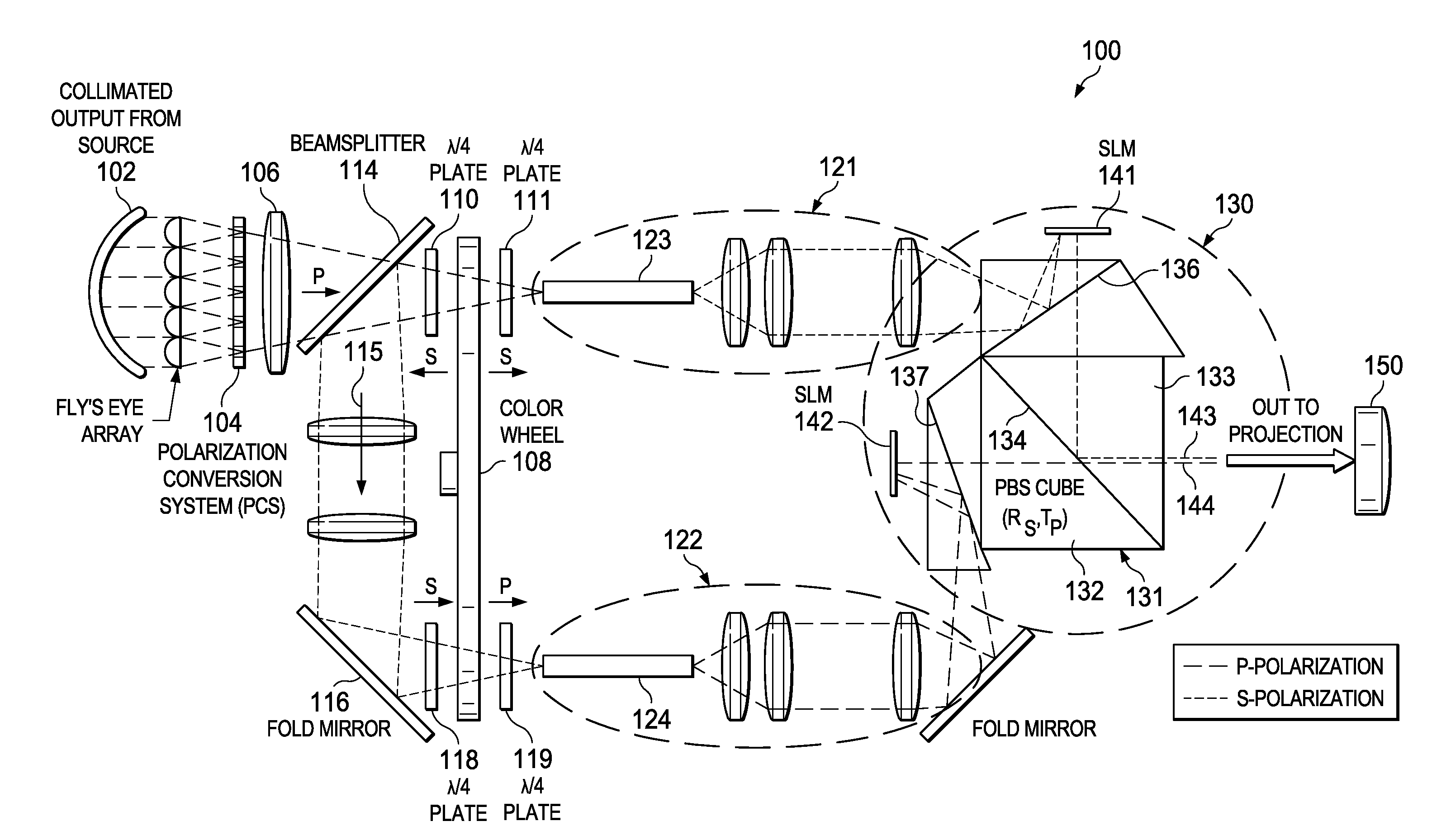
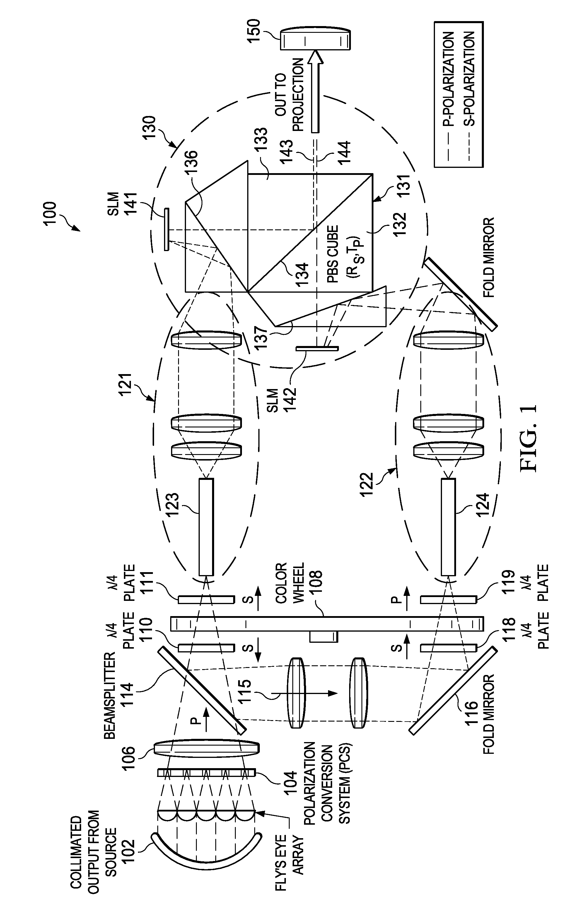
[0017]Embodiments of this invention provide a solution to the problem of recapturing unused light from a source that is filtered by a color wheel in a color-field sequential display system such as a DLP™ projector. A high brightness display system employing a color wheel and multiple spatial light modulators is disclosed herein. Since two-thirds of the light from a light source is filtered out by the color wheel, a solution is to recapture that ‘unused’ light and let it enter the system at a different location, incident onto another modulation panel. This solution is considered a ‘two-chip’ solution with many advantages that will be described in more detail below. The display system uses both the transmitted and the reflected light from the color wheel in producing images. S...


PUM


Abstract

An image may be formed in a projection system by forming a light beam with substantially a first polarization. The light beam is directed onto a first color wheel that transmits a first selected color portion of the light beam and reflects a second color portion of the light beam. The reflected second color portion is converted to a second polarization. A first portion of the image is produced with a first spatial light modulator using the first selected color portion of the light beam having the first polarization. A second portion of the image is produced with a second spatial light modulator using at least a portion of the reflected second color portion of the light beam having the second polarization. The first portion of the image and the second portion of the image are combined to form a combined image for projection.

Description

CLAIM OF PRIORITY UNDER 35 U.S.C. 119(E)[0001]The present application claims priority to and incorporates by reference U.S. Provisional Application No. 62 / 068,908, (attorney docket TI-75574PS) filed Oct. 27, 2014, entitled “COLOR RECAPTURE USING POLARIZATION RECOVERY IN A COLOR-FIELD SEQUENTIAL DISPLAY SYSTEM.”BACKGROUND OF THE INVENTION[0002]1. Field of the Invention[0003]Embodiments of the present invention generally relate to improving light efficiency in a color projection system.[0004]2. Description of the Related Art[0005]Color-field sequential display systems such as a DLP projector often require a color wheel in order to sequentially display red, green, and blue light onto a modulation panel. At any moment in time, the modulation panel is seeing a single color. The color wheel filters the white light from a light source, such as a lamp, into Red, Green, and Blue as it rotates. At any moment in time, only approximately one third of the light is transmitted through the system ...

Claims


Application Information

Patent Timeline
IPC IPC(8): H04N9/31G02B27/28G02B26/08G02B26/00G02B27/14G02B30/25
CPCH04N9/3111H04N9/3167G02B26/008G02B27/141G02B27/286H04N9/3161G02B26/0833G02B27/283G02B27/145G02B27/0961G02B27/0994H04N9/3114H04N9/3158G03B21/008G03B21/2066G03B21/2073G03B33/08G03B35/22G03B37/04G03B21/206H04N13/337H04N9/3117H04N9/3105G02B30/25
Inventor LYUBARSKY, ALEXANDERPETTITT, GREGORY SCOTT
Owner TEXAS INSTR INC
Why Eureka
Try Eureka