

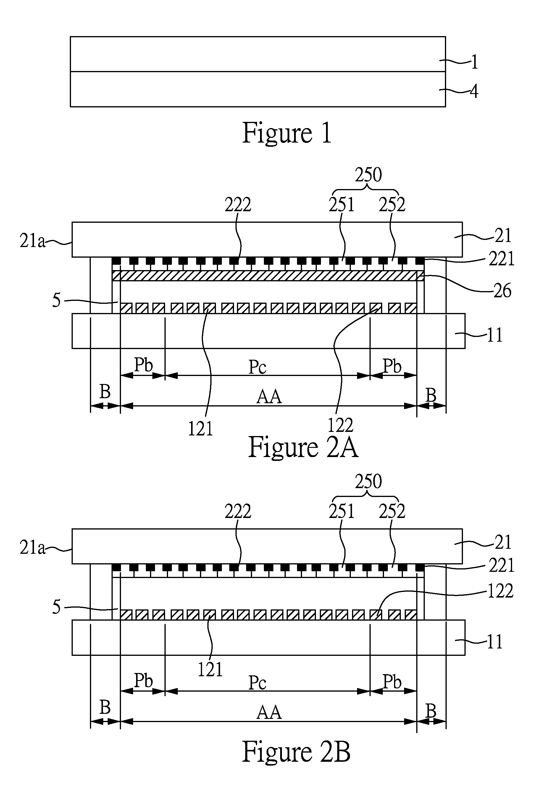
Display panel
- Summary
- Abstract
- Description
- Claims
- Application Information
AI Technical Summary
Benefits of technology
Problems solved by technology
Method used
Image

Examples
embodiment 1 and embodiment 2
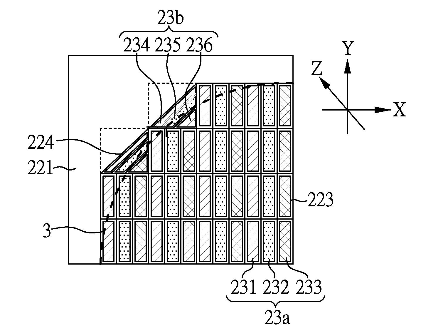
[0059]FIG. 6 shows a schematic diagram of parts of the free-form display panels according to Embodiments 1 and 2, wherein the region represented by the hatched line in the pixel units refers to the light output area. Except for the structures of the border pixel units, other structures are the same as in Comparative Embodiment 1. When the free-form display panel of Embodiment 1 has the structure shown in FIGS. 2B and 3, the schematic diagrams of its border pixel units are shown in FIGS. 7A to 7C; and when the free-form display panel of Embodiment 2 has the structure shown in FIG. 2A, the schematic diagrams of its border pixel units are shown in FIGS. 8A to 8C. Embodiments 1 and 2 have the same central pixel unit structure as Comparative Embodiment 1, and the same features will not be repeated herein for brevity.
[0060]As shown in FIG. 7A and FIG. 8A, the aperture ratio of the border pixel black matrix 224 can be altered to make the border pixel unit more close to the curved trend lin...
embodiment 3 and embodiment 4
[0063]FIG. 9 shows a schematic diagram of parts of the free-form display panels according to Embodiments 3 and 4, wherein the region represented by the hatched line in the pixel units refers to the light output area. Except for the structures of the border pixel units, other structures are the same as in Comparative Embodiment 1. When the free-form display panel of Embodiment 3 has the structure shown in FIGS. 2B and 3, the schematic diagrams of its central pixel units and border pixel units are shown in FIGS. 10A to 10B; and when the free-form display panel of Embodiment 4 has the structure shown in FIG. 2A, the schematic diagrams of its central pixel units and border pixel units are shown in FIGS. 11A and 11B.
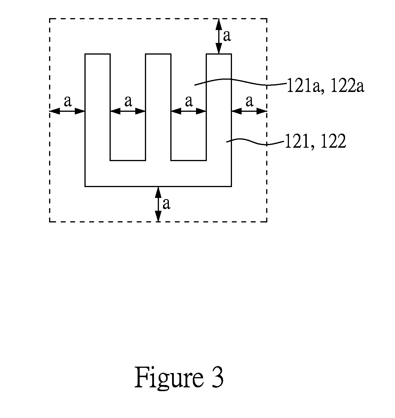
[0064]As shown in FIGS. 10A to 11B, in Embodiments 3 and 4, the first central sub-pixel unit 231, the second central sub-pixel unit 232, and the third central sub-pixel units 23 correspond to the first electrode 121, while the first border sub-pixel unit 234, the second borde...
embodiment 5 and embodiment 6
[0065]FIG. 12 shows a schematic diagram of parts of the free-form display panels according to Embodiments 5 and 6, wherein the region represented by the hatched line in the pixel units refers to the light output area. Except for the structures of the border pixel units, other structures are the same as in Comparative Embodiment 1. When the free-form display panel of Embodiment 5 has the structure shown in FIGS. 2B and 3, the schematic diagram of its central pixel units is shown in FIG. 13A, the schematic diagrams of its border pixel units are shown in FIGS. 13B and 13C; and when the free-form display panel of Embodiment 6 has the structure shown in FIG. 2A, the schematic diagrams of its central pixel units are shown in FIG. 14A, the schematic diagrams of its border pixel units are shown in FIGS. 14B and 14C.
[0066]By comparing FIG. 13A with FIG. 13B, or comparing FIG. 14A with FIG. 14B, it can be seen that in Embodiments 5 and 6, in a part of the border pixel units 23b, widths T2 (de...
PUM
 Abstract
Description
Claims
Application Information