Optical Communication Systems and Methods

a communication system and optical technology, applied in the field of optical communication systems and methods, can solve the problems of limited acoustic communication systems, interference in performance, and inability to permit video or other high-rate data transfers, and achieve the effect of improving optical communication

Inactive Publication Date: 2016-05-05
WOODS HOLE OCEANOGRAPHIC INSTITUTION
View PDF12 Cites 66 Cited by
  • Summary
  • Abstract
  • Description
  • Claims
  • Application Information

AI Technical Summary

Benefits of technology

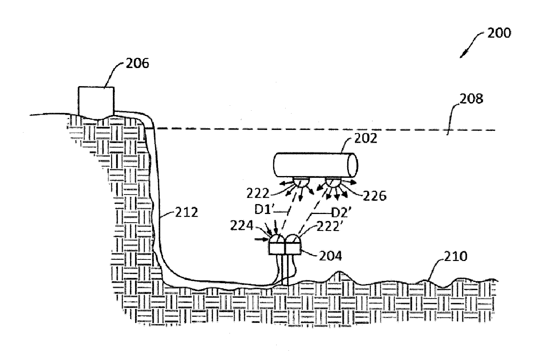
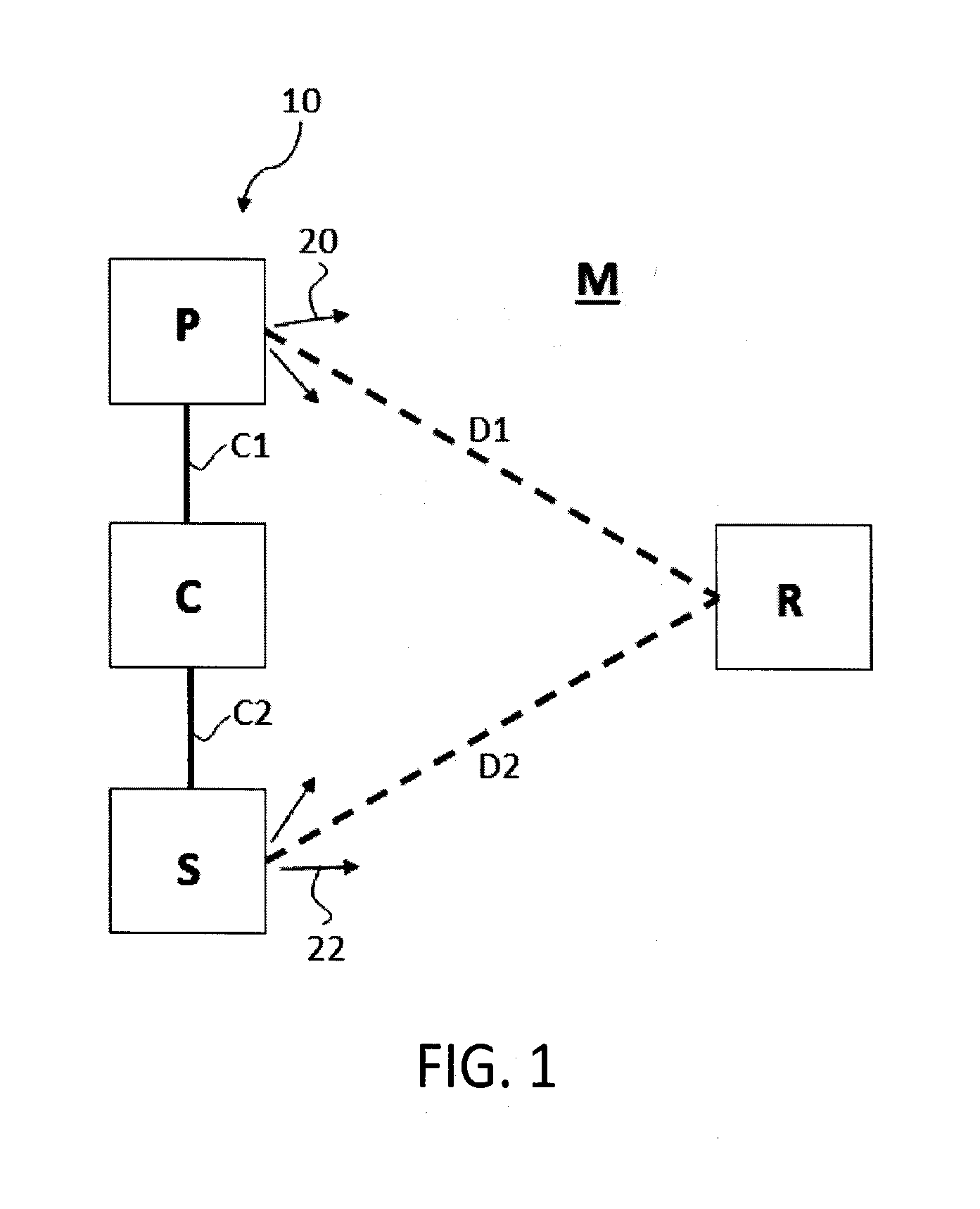
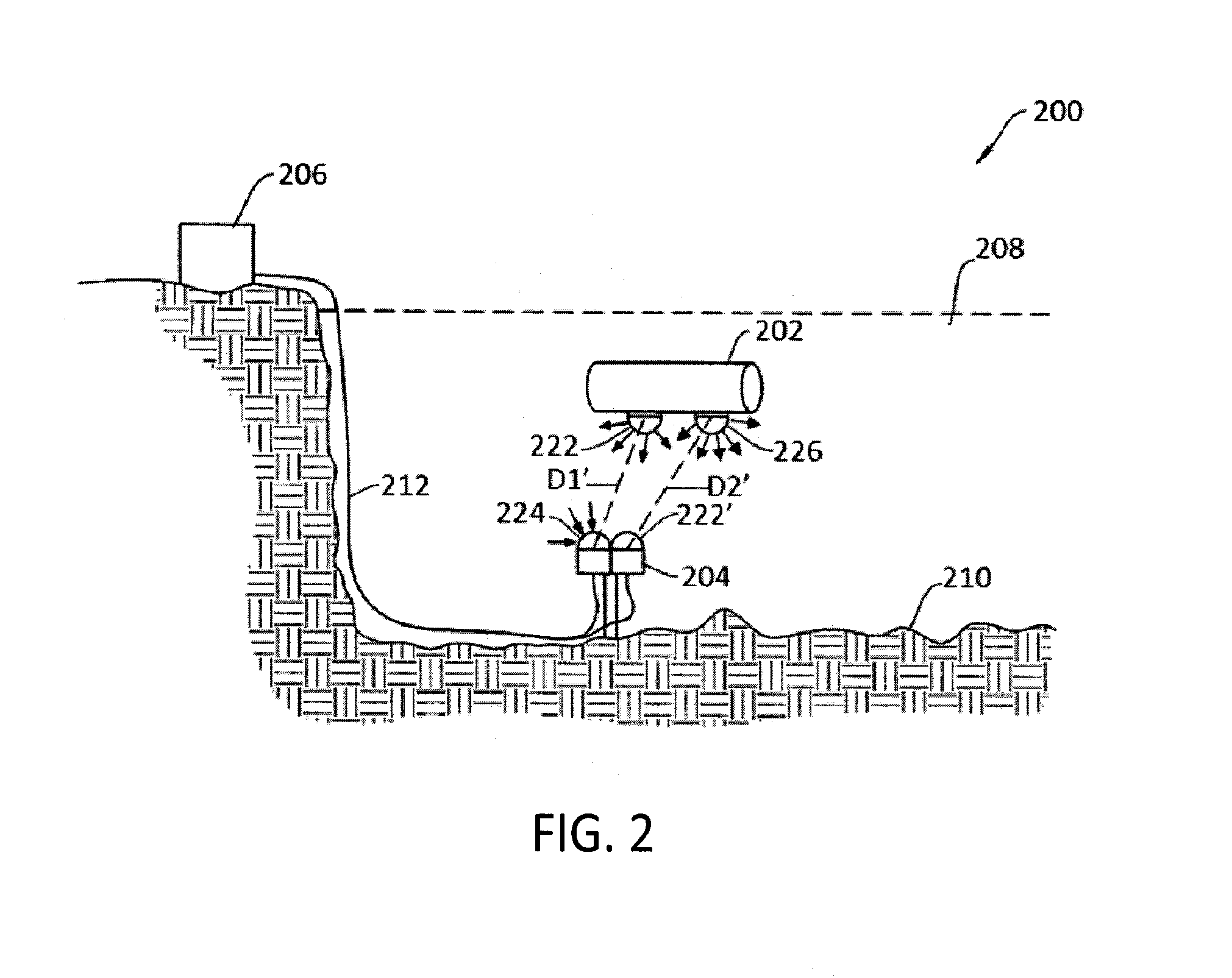
[0010]An object of the present invention is to improve optical communication among a plurality of communication nodes in at least one amorphous medium of a gas such as air, of a liquid such as water, and / or a vacuum.
[0011]Another object of certain aspects of the present invention is to reduce fouling of a surface of an optically transparent element utilizing a light source. By using LEDs in certain embodiments, such a system may be more efficient, have a longer lifetime, and be more compact than traditional systems. The systems and methods may be further augmented by varying wavelengths and duty cycle.
[0013]This invention features a system and method to reduce fouling of a surface subjected to an aquatic environment with a light source. According to one aspect, an antifouling system including an LED for emitting UV radiation, one or more mounts for directing emitted UV radiation toward the surface, and control circuitry for driving the LED disposed in a watertight housing. According to another aspect, an antifouling system which employs a fluorescent lamp as the source of antifouling radiation which is disposed within a pressure vessel including a UV-transmissive material to allow UV light to pass through the pressure vessel and reduce bio-fouling of any surface.
[0015]In some embodiments, the system includes an end cap adapted to provide mechanical and electrical connections to an object such as a node, an observatory, a transducer, an optical modem, a vehicle, an AUV, and ROV, an UUV, a winch, a dock and a profiler. In one embodiment, the system further includes a configurable optical reflector capable of tailoring the UV emission to at least one of a wider angle pattern and a narrower angle pattern relative to the first pattern of the emission. In certain embodiments, the surface is a cable, a winch, a spool, a fin, a propeller, a light, a sensor, a transducer, an optically transparent surface, a window, a camera window, a lens, or a surface unsuitable for an antifouling coating. In one embodiment, the system is capable of reducing biofouling of the surface when disposed a distance from the surface of at least 30 cm.

Problems solved by technology

Such acoustic communication systems, however, are limited by low band-width and high latency, and do not permit video or other high-rate data transfers.
While opticom systems provide high-band-width, bidirectional wireless underwater optical communications, their performance is subject to interference from light generated from secondary light-producing systems deployed within the nearby marine environment.
However, in many circumstances a coating will not work.
For example, windows of a submerged precision optical instrument cannot be coated due to concerns with obstructing the clarity of the windows, thereby affecting the instrument's measurements.
Another approach is to remove the organisms manually, such as by scrubbing with wiping by a mechanism akin to a windshield wiper, but the use of mechanical components can increase the opportunities for failure and introduce additional complexity and cost into the system.
While certain types of UUVs are tethered by cable to the seafloor observatories, the tethered UUVs have a short range of motion and are limited by the length of the tether.
Acoustic communication systems, however, tend to be limited by low bandwidth and high latency, and do not permit video or other high-rate data transfers.

Method used


Image

  • Optical Communication Systems and Methods
  • Optical Communication Systems and Methods
  • Optical Communication Systems and Methods

Examples


Embodiment Construction

[0046]This invention may be accomplished by a system and method to reduce fouling of a surface subjected to an aquatic environment with a light source. According to one aspect, an antifouling system including an LED for emitting UV radiation, one or more mounts for directing emitted UV radiation toward the surface, and control circuitry for driving the LED disposed in a watertight housing. According to another aspect, an antifouling system which employs a fluorescent lamp as the source of antifouling radiation which is disposed within a pressure vessel including a UV-transmissive material to allow UV light to pass through the pressure vessel and reduce bio-fouling of any surface.

[0047]Examples of systems and methods according to the present invention for treating surfaces such as optical elements are described below in particular regarding FIGS. 7A-10B. Various novel optical communication systems that may include antifouling capabilities are described below in relation to the other ...


PUM

PropertyMeasurementUnit
wavelength rangeaaaaaaaaaa
depthaaaaaaaaaa

Abstract

A system and method to reduce fouling of a surface subjected to an aquatic environment with a light source. According to one aspect, an antifouling system including an LED for emitting UV radiation, one or more mounts for directing emitted UV radiation toward the surface, and control circuitry for driving the LED disposed in a watertight housing. According to another aspect, an antifouling system which employs a fluorescent lamp disposed within a pressure vessel including a UV-transmissive material to allow UV light to pass through the pressure vessel and reduce bio-fouling of any surface.

Description

CROSS-REFERENCE TO RELATED APPLICATIONS[0001]This application is a continuation-in-part of (a) U.S. application Ser. No. 14 / 557,361 filed 1 Dec. 2014, which is a continuation-in-part of: (i) U.S. application Ser. No. 13 / 117,867 filed 27 May 2011, which is a continuation of U.S. application Ser. No. 11 / 348,726 filed 6 Feb. 2006, now U.S. Pat. No. 7,953,326; and (ii) U.S. application Ser. No. 13 / 344,430 filed 5 Jan. 2012, now U.S. Pat. No. 8,953,944; and is a continuation-in-part of (b) U.S. application Ser. No. 13 / 940,814 filed 12 Jul. 2013, and claims priority to U.S. Provisional Application Nos. 61 / 430,081 and 61 / 671,426 filed 5 Jan. 2011 and 13 Jul. 2012, respectively. The entire contents of each of the above-mentioned applications are incorporated herein by reference.STATEMENT REGARDING GOVERNMENT LICENSE RIGHTS[0002]The invention described in U.S. application Ser. No. 13 / 940,814 filed 12 Jul. 2013 was made with U.S. government support under Grant Nos. OCE-0942835 and OCE-0737958...

Claims


Application Information

Patent Timeline
Patent Type & Authority Applications(United States)
IPC IPC(8): A61L2/10G02B19/00
CPCA61L2/10G02B19/0095G02B19/0019H04B13/02H04B10/80Y10T29/49826
Inventor FARR, NORMAN E.PONTBRIAND, CLIFFORD T.
Owner WOODS HOLE OCEANOGRAPHIC INSTITUTION
Why Eureka
Try Eureka