Air blowing device
Inactive Publication Date: 2016-05-05
HOWA PLASTICS CO LTD +1
8 Cites 1 Cited by
AI-Extracted Technical Summary
Problems solved by technology
However, when the mask is inadvertently arranged in the vicinity of the air outlet of the related-art device, the flow direction of the blowing airflow may be changed to an unintended direction due to the mask though the air outlet may be kept invisible.
That is, when...
Benefits of technology
[0017]In addition, the air blowing device according to the one embodiment of the present invention can keep the air outlet invisible to the extent possible without impairing the function as the air blowing device to adjust the flow direction of the blowing airflow.
[0018]Further, the air blowing device according to the one embodiment of the present invention does not require an airflow direction adjustment mechanism such as a fin unlike the related-art device, and hence the air outlet can also be further narrowed as compared to that in the related-art device. In addition, not only the air outlet but also the air blowing device itself may be less likely to be recognized by the user or the like with the use of the air blowing device according to the one embodiment of the present invention, in particular, the guide wall as a part of another interior comp...
Abstract
An air blowing device capable of keeping an air outlet invisible to the extent possible without impairing a function as the air blowing device, including: a tubular body defining an airflow passage and an air outlet; a guide wall for guiding an airflow having passed through the air outlet in an intended direction; and an on-off valve forming a part of the guide wall, which is capable of opening or closing a concave portion formed in the guide wall. The guide wall has a convex surface shape protruding in a direction intersecting with a forward direction of the air outlet, and is arranged so that a projection image, which is obtained by projecting the guide wall onto an imaginary plane including the air outlet, covers the entire air outlet. The on-off valve is configured to open or close the concave portion in accordance with the intended direction.
Application Domain
Ducting arrangementsAir-treating devices +3
Technology Topic
Projection imageAirflow +1
Image
Examples
- Experimental program(1)
Example
[0037]Now, an air blowing device according to embodiments of the present invention is described referring to the drawings.
[0038]
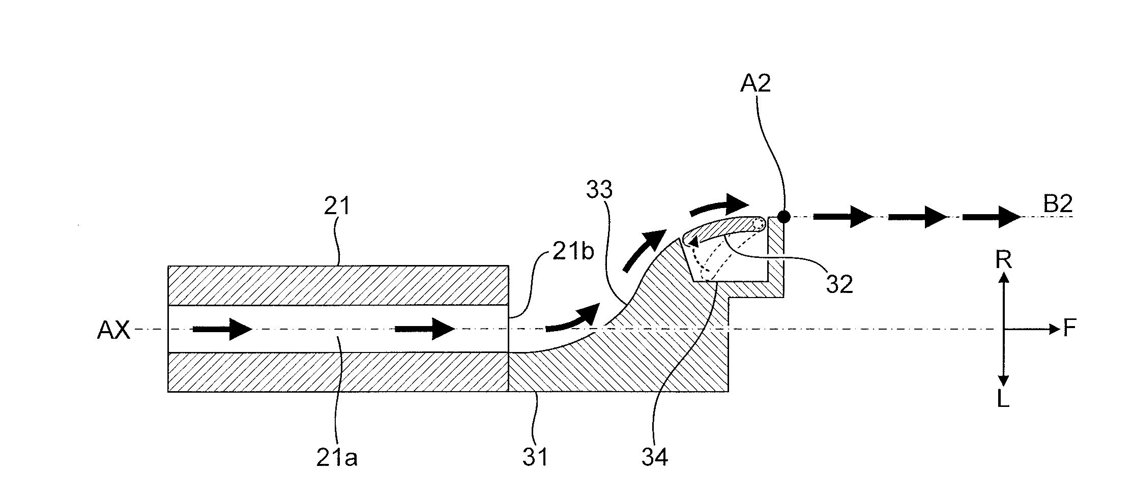
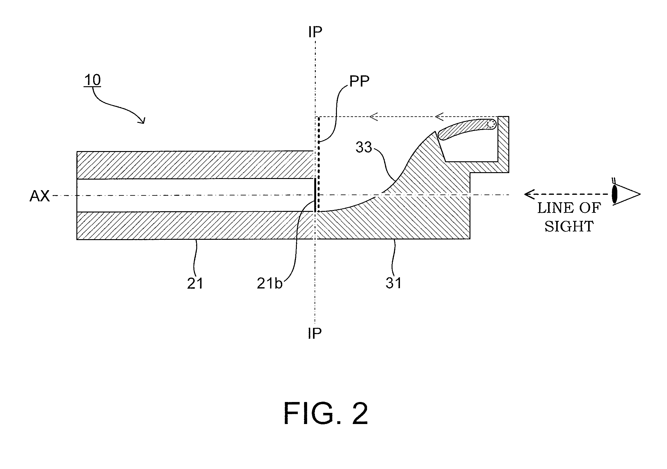
[0039]FIG. 1 is an illustration of a schematic configuration of an air blowing device 10 according to an embodiment of the present invention (hereinafter referred to as “embodiment device 10”). The embodiment device 10 is installed on an instrument panel of an automobile so as to be interposed between a peripheral component P1 and a peripheral component P2. Note that, in this embodiment, the peripheral component P1 is a housing of the instrument panel, and the peripheral component P2 is an exterior portion of a display of a car navigation system.
[0040]Specifically, the embodiment device 10 includes a hollow columnar portion for allowing an airflow to pass therethrough (tubular body 21 described later), and a shelf-like portion, i.e. a rising portion like a continental slope adjacent to a continental shelf, for allowing the airflow to be guided along a curved wall surface (guide wall 31 described later). FIG. 1 is a schematic sectional view for illustrating the embodiment device 10 when the embodiment device 10 is cut along a plane parallel to an axial line AX of the embodiment device 10 in a lateral direction (in a direction from a right side R to a left side L described later). In other words, FIG. 1 is a schematic sectional view for illustrating the embodiment device 10 when the embodiment device 10 is viewed from above.
[0041]For the sake of convenience, a direction toward a front side of the embodiment device 10 along the axial line AX is hereinafter referred to as “forward direction F,” and directions orthogonal to the forward direction F toward right and left sides of the embodiment device 10 are hereinafter referred to as “rightward direction R” and “leftward direction L,” respectively. Note that, the rightward and leftward directions are defined based on rightward and leftward directions when a user of the automobile views the embodiment device 10 mounted on a periphery of a dashboard of the automobile or the like.
[0042]As illustrated in FIG. 1, the embodiment device 10 includes the tubular body 21 and the guide wall 31 including an on-off valve 32 forming a part of the guide wall 31. Now, structures of those members are described in more detail.
[0043]The tubular body 21 defines an airflow passage 21a thereinside and an air outlet 21b in an end portion thereof in the forward direction F. Note that, the tubular body 21 is a tubular body having a substantially rectangular parallelepiped shape, and the air outlet 21b has a substantially rectangular shape when viewed from the front side F. Further, the guide wall 31 is formed on a downstream side with respect to the air outlet 21b of the tubular body 21, for guiding an airflow having passed through the air outlet 21b in an intended direction. Note that, a width of the guide wall 31 in a vertical direction (direction perpendicular to the drawing sheet) is substantially equal to a width of the tubular body 21 in the vertical direction. With those structures, air, which has flowed from an opening portion 21c of the tubular body 21 on a rear side (side opposite to the front side F), passes through the airflow passage 21a. The air is then blown from the opening portion (air outlet 21b) on the front side F, and is guided (led) in the intended direction along the guide wall 31. The arrows in FIG. 1 indicate the flow of the air.
[0044]Note that, the amount of the air supplied to the embodiment device 10 (amount of the air flowing from the opening portion 21c of the embodiment device 10 on the rear side into the airflow passage 21a, that is, flow rate of the airflow passing through the airflow passage 21a and then the air outlet 21b) may be adjusted by operating as necessary a flow rate adjustment valve (not shown) arranged inside or outside the embodiment device 10, a pump (not shown) for supplying air to the embodiment device 10, or the like.
[0045]The guide wall 31 has a wall surface 33 having a convex surface shape (curved surface having a convex shape). The wall surface 33 of the guide wall 31 protrudes in a direction intersecting with the forward direction F of the air outlet 21b (extending direction of a straight line passing through a center point 21b1 of an opening plane of the air outlet 21b so as to be orthogonal to the opening plane). Specifically, the forward direction F of the air outlet 21b is an extending direction of the axial line AX in FIG. 1, and the wall surface 33 of the guide wall 31 protrudes from the left side L to the right side R in FIG. 1.
[0046]Further, as illustrated in FIG. 2, the guide wall 31, specifically, the wall surface 33 is arranged so that a projection image PP, which is obtained by projecting the guide wall 31 (wall surface 33) onto an imaginary plane IP including the air outlet 21b, covers the entire air outlet 21b.
[0047]Therefore, when the user of the automobile or the like views the embodiment device 10 from the front side of the embodiment device 10 (that is, along the projection direction) as indicated by the line of sight in FIG. 2, the air outlet 21b is hidden by the guide wall 31 so that the air outlet 21b is not visually recognized by the user or the like.
[0048]Referring to FIG. 1 again, the on-off valve 32 is a plate body having a substantially rectangular shape in plan view. The on-off valve 32 is curved in conformity with the shape of the wall surface 33 of the guide wall 31 to form a part of the guide wall 31, specifically, a part of the wall surface 33. The on-off valve 32 is capable of opening or closing a concave portion 34 formed in the guide wall 31 by pivoting about a pivot axis 32a. In other words, the on-off valve 32 is supported on the guide wall 31 so as to be pivotable between a pivot angle at which the concave portion 34 is opened and a pivot angle at which the concave portion 34 is closed.
[0049]Note that, the on-off valve 32 is configured such that the pivot angle of the on-off valve 32 is operable by the user. For example, the on-off valve 32 is configured such that the pivot angle is operable by the user through intermediation of a link member (not shown), or that the pivot angle is operable through actuation of a motor (not shown) in accordance with an instruction from the user.
[0050]The concave portion 34 is a hollow portion having a shape recessed from the wall surface 33 of the guide wall 31 to an inside of the guide wall 31. The concave portion 34 has dimensions such as a depth and width that allow the on-off valve 32 to be pivotable as described above. Further, as illustrated in a partially enlarged view of FIG. 1, the concave portion 34 is formed so that an angle θ formed between a wall surface 33a of the guide wall, which is formed on an upstream side with respect to the concave portion 34 and adjacent to the concave portion 34, and a side surface 34a of the concave portion, which is adjacent to the wall surface 33a, becomes a predetermined angle smaller than 90° (acute angle).
[0051]The overview of the embodiment device 10 is described above.
[0052]
[0053]Next, actual actuation of the embodiment device 10 is described.
[0054]The embodiment device 10 is configured to adjust a flow direction of the blowing airflow by changing the pivot angle of the on-off valve 32 to change a separating position of the airflow. Now, the adjustment of the blowing airflow by the embodiment device 10 is described referring to FIG. 3 and FIG. 4. FIG. 3 and FIG. 4 are schematic sectional views for illustrating the embodiment device 10 when the embodiment device 10 is cut along the plane parallel to the axial line AX of the embodiment device 10 in the lateral direction similarly to FIG. 1. Note that, in FIG. 3 and FIG. 4, for the sake of convenience, the illustration of the peripheral components P1 and P2 is omitted.
[0055]As illustrated in FIG. 3, the airflow, which has flowed from the opening portion 21c of the embodiment device 10 on the rear side into the airflow passage 21a, passes through the air outlet 21b, and then flows along the wall surface 33 of the guide wall 31 due to the Coanda effect. As illustrated in FIG. 3, when the pivot angle of the on-off valve 32 is the “pivot angle at which the concave portion 34 is opened,” the airflow, which has flowed along the wall surface 33 of the guide wall 31, faces the concave portion 34. At this time, an adhesive force obtained by the Coanda effect is lost in the concave portion 34 so that the airflow is separated from the wall surface 33 of the guide wall 31 at a position at which the concave portion 34 is formed (separating position A1). Then, the airflow is caused to flow in a tangential plane direction of the wall surface 33 of the guide wall 31 at the separating position A1 (tangential direction B1 in FIG. 3). As a result, the flow direction of the blowing airflow is adjusted to the rightward direction R of the embodiment device 10. As an indicator of the flow direction of the blowing airflow, for example, an angle formed between the axial line AX of the embodiment device 10 and the flow direction B1 of the blowing airflow is an angle α.
[0056]Next, as illustrated in FIG. 4, when the pivot angle of the on-off valve 32 is the “pivot angle at which the concave portion 34 is closed,” the airflow having passed through the airflow passage 21a is caused to flow along a surface of the on-off valve 32 without facing the concave portion 34. Then, the airflow is separated from the wall surface 33 of the guide wall 31 at a distal end portion (separating position A2) of the guide wall 31, which is formed on the downstream side with respect to the separating position A1. Then, the airflow is caused to flow in a tangential plane direction of the wall surface 33 of the guide wall 31 at the separating position A2 (tangential direction B2 in FIG. 4). As a result, the flow direction of the blowing airflow is adjusted to the forward direction F of the embodiment device 10. As an indicator of the flow direction of the blowing airflow, for example, an angle formed between the axial line AX of the embodiment device 10 and the flow direction B2 of the blowing airflow is an angle of 0°, which is smaller than the angle α (that is, the axial line AX and the flow direction B2 are parallel to each other).
[0057]As described above, the embodiment device 10 is capable of adjusting the flow direction (B1, B2) of the blowing airflow as well as changing the separating position (A1, A2) by opening or closing the on-off valve 32 forming a part of the wall surface 33 of the guide wall 31. Specifically, the embodiment device 10 is capable of switching the flow direction of the blowing airflow between the rightward direction R of the embodiment device 10 and the forward direction F thereof.
[0058]The actual actuation of the embodiment device 10 is described above.
[0059]As described above, the embodiment device 10 includes the tubular body 21, the guide wall 31, and the on-off valve 32, which are structured as described above. With this, the embodiment device 10 can adjust the flow direction of the blowing airflow while preventing the air outlet 21b from being visually recognized by the user (keeping the air outlet 21b invisible).
OTHER EMBODIMENTS
[0060]The present invention is not limited to the above-mentioned embodiment, and various modifications may be employed within the scope of the present invention.
[0061]For example, the embodiment device 10 has a single concave portion 34 and a single on-off valve 32 in the guide wall 31. However, the number of the on-off valves 32 is not necessarily one. For example, as illustrated in FIG. 5, a plurality of the concave portions (two concave portions 34x and 34y in this embodiment) and a plurality of the on-off valves (two on-off valves 32x and 32y in FIG. 5) may be formed in the guide wall 31. With the plurality of the on-off valves, the flow direction of the blowing airflow can more precisely be adjusted than in the case where the single concave portion is formed.
[0062]Further, the embodiment device 10 is mounted inside a vehicle cabin of the automobile (inner panel). However, the air blowing device of the present invention may be mounted on another portion such as a pillar portion inside the vehicle cabin of the automobile. In addition, the air blowing device of the present invention is not limited to the one mounted inside the vehicle cabin of the automobile, and, for example, may be mounted to such various members that air supply and stop of the air supply are desired.
PUM


Description & Claims & Application Information
We can also present the details of the Description, Claims and Application information to help users get a comprehensive understanding of the technical details of the patent, such as background art, summary of invention, brief description of drawings, description of embodiments, and other original content. On the other hand, users can also determine the specific scope of protection of the technology through the list of claims; as well as understand the changes in the life cycle of the technology with the presentation of the patent timeline. Login to view more.
Similar technology patents
Settling tank and method of operating the same
Owner:KURITA WATER INDUSTRIES LTD
Classification and recommendation of technical efficacy words
- prevent stagnation
Settling tank and method of operating the same
Owner:KURITA WATER INDUSTRIES LTD