
Lollipop discharging device

A technology for lollipops and driving devices, which is applied in confectionery, confectionery industry, food science and other directions, can solve the problems of low efficiency and quality of unloading, complicated process of inserting sticks, and low quality of inserting sticks, etc. The effect of being too complicated, reducing operating procedures and improving production efficiency

Pending Publication Date: 2020-08-07
汕头市核新达机械有限公司
View PDF7 Cites 0 Cited by
  • Summary
  • Abstract
  • Description
  • Claims
  • Application Information

AI Technical Summary

Problems solved by technology

[0005] The object of the present invention is to provide a lollipop lowering device, by setting at least one feeding channel in the hopper in conjunction with the feeding inclined surface, and configuring a driving assembly outside the hopper, the driving assembly inserted into the hopper is driven by a separate driving device Carry out reciprocating motion to avoid the sticking phenomenon of the stick during the falling process, and then drive the stick to fall smoothly, and transmit the falling stick to the stick outlet channel through the stick feeding mechanism, so as to solve the problem of lollipop unloading in the prior art. The structure of the device is complex, the processing cost is high, the process of inserting the rod is complicated, it is easy to cause damage to the rod, the efficiency and quality of the lower rod are lower, and the quality of the inserted rod is lower.

Method used


Image

  • Lollipop discharging device
  • Lollipop discharging device

Examples


Embodiment

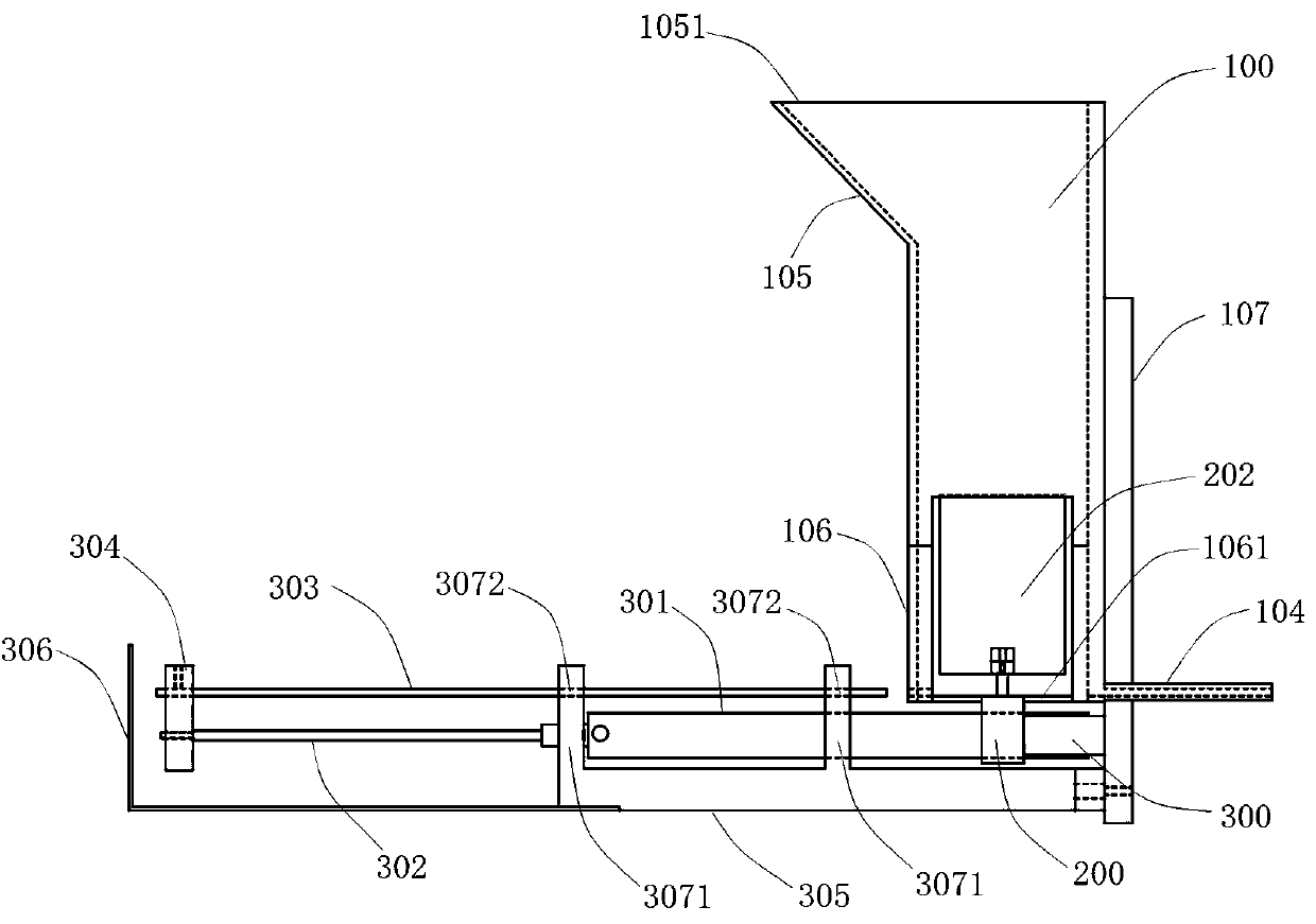
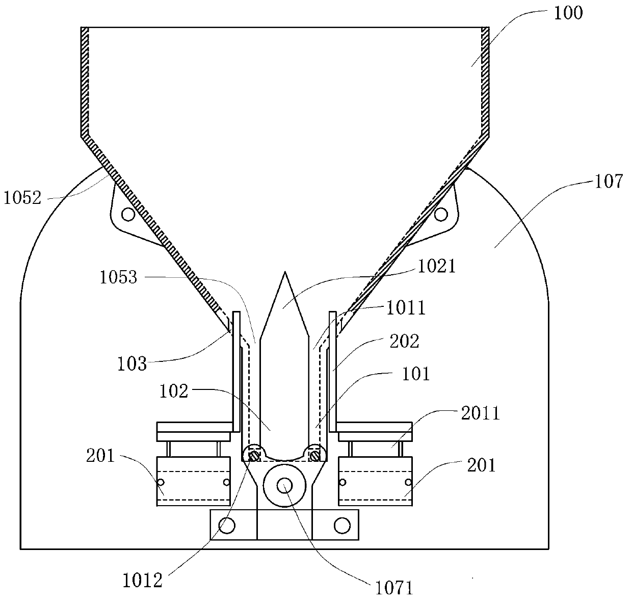
[0035] Such as Figure 1-2 , The lollipop unloading device includes a hopper 100 , a splitter assembly 102 , a drive assembly 202 , a separation drive device 200 , a stick outlet channel 104 , and a stick feeding mechanism 300 .

[0036] Wherein, the hopper 100 is provided with a feeding part 105 and a base part 106. The feeding part 105 is installed on the top of the base part 106, and has a feeding inclined surface inclined outwards from the tops of both sides of the base part 106. Inside the base part 106 The feeding inclined surface has at least one feeding channel 101 . The hopper 100 has a hopper inlet 1051 and a hopper outlet 1061 , the hopper inlet 1051 is formed at the top of the feeding part 105 , and the hopper outlet 1061 is formed at the bottom of the base part 106 . The feed channel 101 has a feed channel inlet 1011 and a feed channel outlet 1012. The feed channel 101 extends from the middle of the hopper 100 to the hopper outlet 1061. The feed channel outlet 10...


PUM


Abstract

A lollipop discharging device disclosed in the invention comprises a hopper, a flow dividing assembly, a driving assembly, a separation driving device, a lollipop discharging channel and a lollipop conveying mechanism, the hopper is composed of a feeding part and a base part, the feeding part is provided with feeding inclined faces inclining outwards from the tops of the two sides of the base part, and the base part is internally matched with the feeding inclined faces to form at least one feeding channel; the flow dividing assembly is arranged in the hopper, and the top of the shunting assembly is matched with the feeding inclined faces to form a conical convex part; the driving assembly is matched with the feeding inclined faces and is symmetrically mounted on two sides of the hopper; the separation driving device is used for driving the driving assembly to reciprocate in a plugging port; the lollipop discharging channel is mounted on one side of the hopper corresponding to the feeding channel; and the lollipop conveying mechanism is installed on the other side and is used for conveying the lollipops falling out of the discharging port of the hopper to the lollipop discharging channel. The lollipop discharging device is used for solving the problems that a lollipop discharging device in the prior art is complex in structure, high in machining cost, low in lollipop dischargingefficiency and not high in lollipop discharging and inserting quality.

Description

technical field [0001] The invention relates to the technical field of lollipop manufacturing equipment, in particular to a lollipop lowering device. Background technique [0002] Most of the traditional lollipops are manually lowered, and the production efficiency is low. In the process of lowering the sticks, the quality of the lower rods is prone to be low, such as inclined or uneven lowering of the sticks, which affects the subsequent rod insertion effect. [0003] At present, although a lowering device is provided for lollipop lowering sticks, most of them are lowered by improving the indexer. For example, the application number is 201911063689.1, and the patent name is "Ejector mechanism for lollipop molding machine and its Lollipop molding machine" patent, the rotation of the forming mold drives the first turntable and the second turntable of the ejector mechanism to rotate synchronously, driving the ejector to push the candy stick in the corresponding stick groove in...

Claims


Application Information

Patent Timeline
Patent Type & Authority Applications(China)
IPC IPC(8): A23G3/02
CPCA23G3/02
Inventor 谢立新郑细芬
Owner 汕头市核新达机械有限公司
Learn More