Settling tank and method of operating the same

Inactive Publication Date: 2015-10-22
KURITA WATER INDUSTRIES LTD
View PDF8 Cites 1 Cited by
  • Summary
  • Abstract
  • Description
  • Claims
  • Application Information

AI Technical Summary

Benefits of technology

[0022]In the settling tank according to the present invention, floc-containing raw water is introduced from the distributor into the lower part or a bottom part of the tank body, and is stirred by the stirring member, whereby flocs grow. The flocs (sludge) flow into the receiving chamber via the outlet provided on the side of the tank body, and are discharged via the sludge-discharging portion of the receiving chamber. In the settling tank according to the present invention, the stirring member is provided between the distributor and the bottom surface of the tank body. Therefore, sedimentation/stagnation of the sludge at the bottom of the tank body is prevented. Accordingly, the sludge is prevented from stagnating at the bottom of the tank body over a long period and undergoing putrefaction or fermentation. Hence, the sludge is prevented from floating upward because of adhesion of gases, such as methane gas and hydrogen sulfide gas, thereto. Consequently, treated water of good quality is obtained over a long period.
[0023]When the stirring member is provided immediately above the bottom surface of the tank body, the stagnation of sludge near the bottom surface of the tank body is more assuredly prevented.
[0024]When the tank body has a circular-cylindrical shape and the rotation diameter of the stirring member is as large as 0.6 to 0.95 times the bore (diameter) of the tank body, the stagnation of sludge is more assuredly prevented over the entirety of the bottom surface of the tank body.
[0025]When the height at which (the lower surface of) the distributor is positioned is as small as 1 to 30% of the height from the bottom surface of the tank body to the sludge outlet, flocs in the floc-containing raw water that flowin

Problems solved by technology

Such gases tend to adhere to the sludge and to make the sludge go up in the tank body and be mixed into supernatant water, deteriorating the quality of the supernatant water (treated water).
In that case, flocs tends to be broken, deteriorating the quality of supernatant water.
Nevertheless, the

Method used


Image

  • Settling tank and method of operating the same
  • Settling tank and method of operating the same
  • Settling tank and method of operating the same

Examples


Example

Example 1

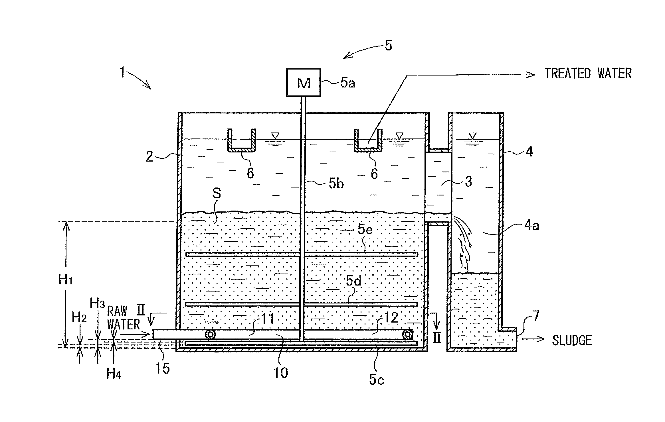
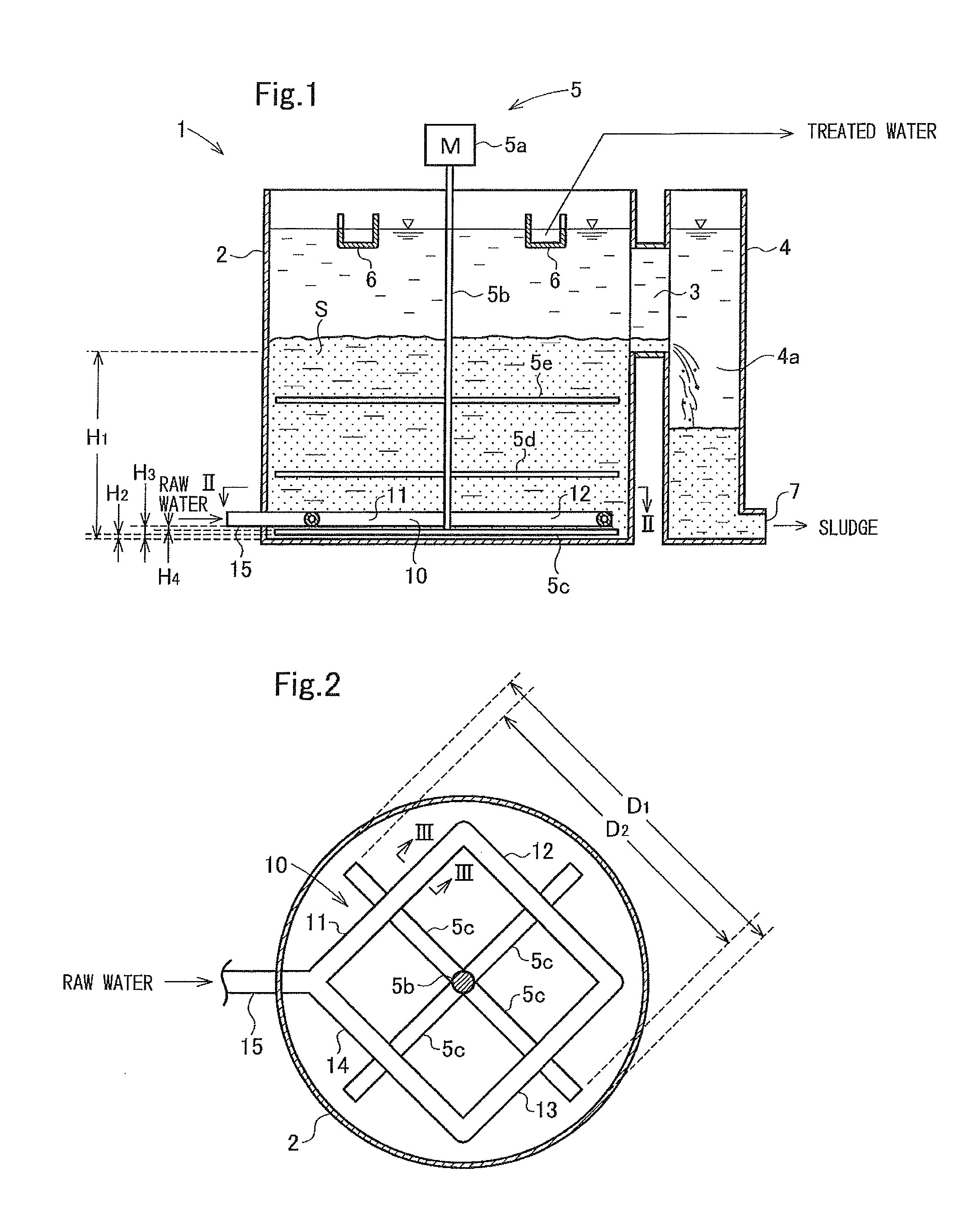
[0066]Using the tank illustrated in FIGS. 1 to 4 and configured as described below, raw water having the following quality was treated.

[0067]SS concentration: 100 mg / L

[0068]pH: 7.3

[0069]Difference in specific gravity from that of in-tank liquid: 0.017

[0070]Size: 1500 mm of diameter, 1500 mm of height

[0071]Horizontal length of stirring wheel: 1.35 m (0.9 times tank bore)

[0072]H1: 0.8 m

[0073]H2: 0.03 m (4% of H1)

[0074]H3: 0.09 m (11% of H1)

[0075]H4: 0.015 m (17% of H3)

[0076]Aluminum sulfate: 300 mg / L

[0077]Cationic polymer: 1 mg / L (Kurifarm PC728 of Kurita Water Industries, Ltd.)

[0078]Anionic polymer: 3 mg / L (Kurifarm PA465 of Kurita Water Industries, Ltd.)

[0079]Water-flow LV: 15 m / hr

[0080]Stirring intensity (G-value):[0081]30 s−1 in area extending from upper surface of distributor to lower end of outlet[0082]88 s−1 in space between lower surface of distributor and bottom of tank

[0083]FIG. 9 illustrates changes in the concentration of SS in treated water that were observed ove...

Example

Comparative Example 1

[0084]Using an apparatus that is the same as that used in Example 1 except that the stirring device 5 is not provided, raw water was treated under the same conditions. FIG. 9 illustrates changes in the concentration of SS in treated water that were observed over time.

[0085][Review]

[0086]As graphed in FIG. 9, in Example 1, treated water containing SS of of 50 mg / L or less was obtained stably for two consecutive days. In contrast, in Comparative Example 1, when about 38 hours had elapsed and when about 43 hours had elapsed, air bubbles were generated in sludge accumulated at the bottom, the air bubbles caused lumps of sludge to float upward, and the quality of treated water was worsened to a SS concentration of 300 mg / L. These results show that stable treated water is obtained by stirring the sludge below the distributor as in Example 1.

[0087]While the present invention has been described in detail as specific embodiments, it is obvious to those skilled in the art...


PUM

PropertyMeasurementUnit
Fractionaaaaaaaaaa
Fractionaaaaaaaaaa
Frequencyaaaaaaaaaa

Abstract

In a settling tank of the invention, treated water has good quality and whose operation is stable over a long period. A settling tank includes a tank body having a circular-cylindrical shape whose axial direction corresponds to the vertical direction, a distributor provided in a lower part (near the bottom) of the tank body, an outlet provided in a middle part or a part slightly above the middle part of a side face of the tank body, a receiving tank communicating with the tank body via the outlet, a stirring device provided in the tank body, a trough for extracting treated water provided in an upper part of the tank body, a sludge discharge port through which concentrated sludge is extracted from a lower part of the receiving tank, and so forth. A stirring member is provided below the distributor.

Description

FIELD OF INVENTION[0001]The present invention relates to a settling tank such as a coagulating sedimentation tank and in particular to a settling tank including a sludge outlet provided in a side face of a tank body thereof. The present invention also relates to a method of operating the settling tank.BACKGROUND OF INVENTION[0002]Facilities such as an activated-sludge treatment facility and a coagulating-sedimentation treatment facility have employed, in general, sedimentation in which a solid-liquid separation tank (a settling tank) is used as means for separating sludge mixture into treated water and sludge. In such sedimentation, a sludge-blanket filtration method is employed in which a sludge zone (a sludge blanket layer) is formed in a sedimentation tank to obtain treated water having good quality by efficiently removing suspensoids and fine SS from the sludge mixture. The sludge mixture is made to flow into a portion below the sludge zone and to flow through the sludge zone, w...

Claims


Application Information

Patent Timeline
IPC IPC(8): B01D21/24C02F1/00
CPCC02F1/00B01D21/2405B01D21/2416B01D21/286C02F1/006C02F2001/007
Inventor SHIMIZU, SATOSHITERASHIMA, MITSUHARU
Owner KURITA WATER INDUSTRIES LTD
Why Eureka
Try Eureka