Eureka AIR delivers breakthrough ideas for toughest innovation challenges, trusted by R&D personnel around the world.

Fluidized bed boiler with a support construction for a particle separator

Active Publication Date: 2016-05-05
SUMITOMO SHI FW ENERGIA OY
View PDF4 Cites 6 Cited by
  • Summary
  • Abstract
  • Description
  • Claims
  • Application Information

AI Technical Summary

Benefits of technology

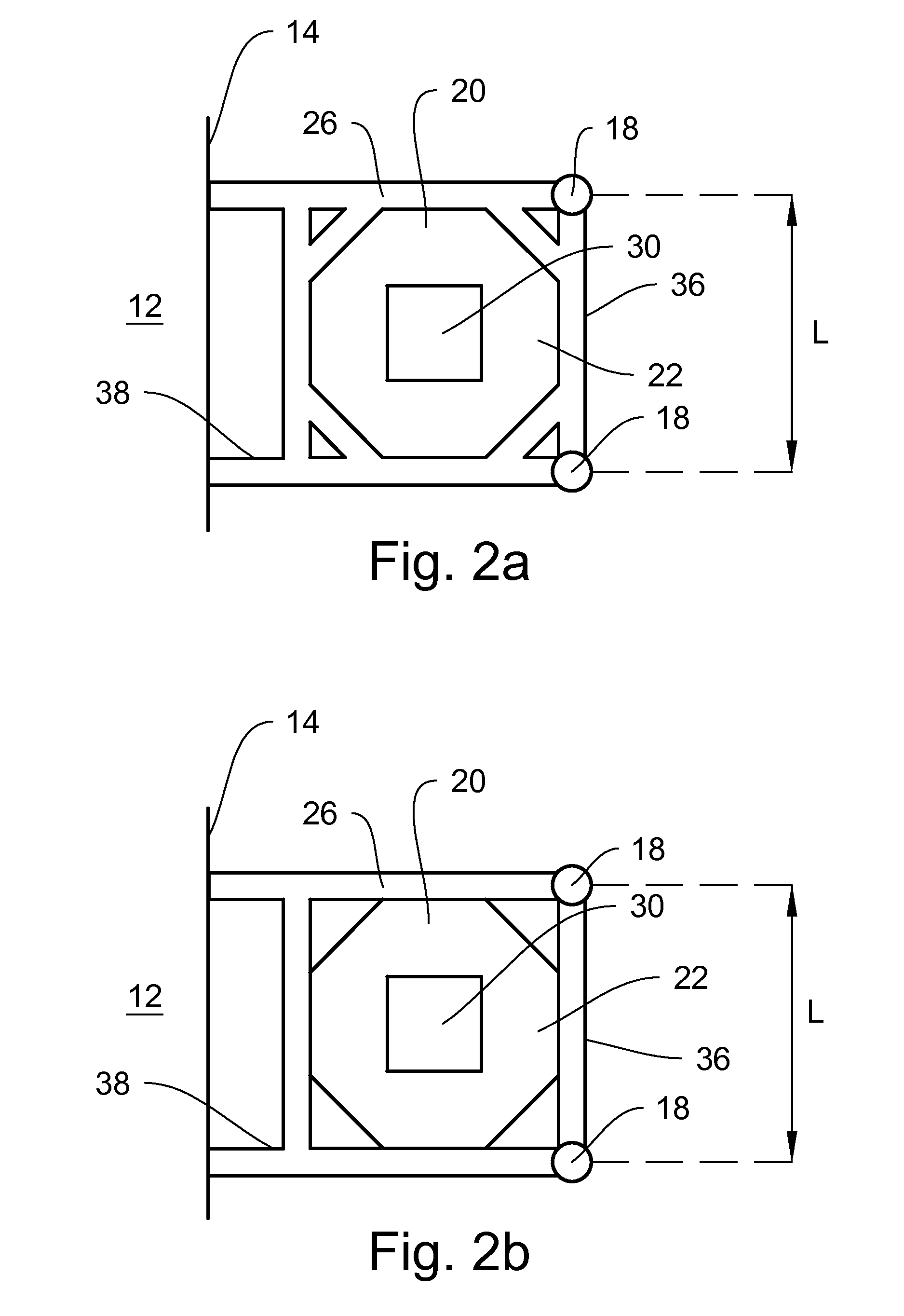
The present invention provides a new solution for supporting the particle separator of a bottom-supported fluidized bed boiler by arranging a frame-like supporting member to surround the conical lower portion of the particle separator and attaching the outboard portion of the supporting member to bottom-supported downcomer pipes. This invention allows for a simple and economically advantageous fluidized bed boiler in which the particle separator can be installed relatively quickly and easily. The supporting member is attached to the side wall of the furnace and to at least two downcomer pipes, providing a very stable support of the particle separator. The weight of the particle separator is carried only by a lower portion of the side wall, minimizing the impact on the side wall. The additional downcomer pipe branches, arranged adjacent to the outer portion of the particle separator, further contribute to a stable support system of the particle separator.

Problems solved by technology

A disadvantage of bottom-supported construction is that the walls have to be strong enough to carry the compression load of the structures above.
A special problem in bottom-supported fluidized bed boilers is the supporting of the particle separator.
A disadvantage of this construction is that the common wall of the two units, i.e., of the furnace and the separator, has to be made especially strong to carry a large portion of the weights of both units.

Method used


Image

  • Fluidized bed boiler with a support construction for a particle separator
  • Fluidized bed boiler with a support construction for a particle separator
  • Fluidized bed boiler with a support construction for a particle separator

Examples


Embodiment Construction

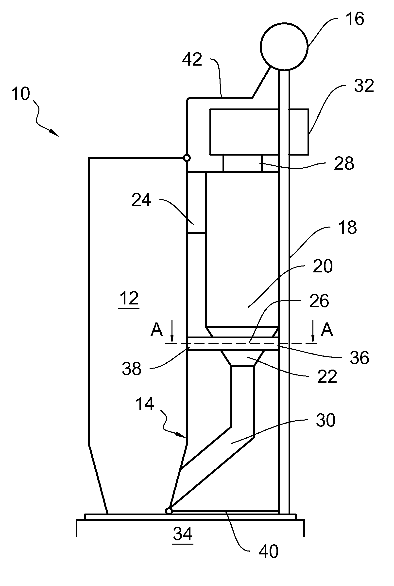
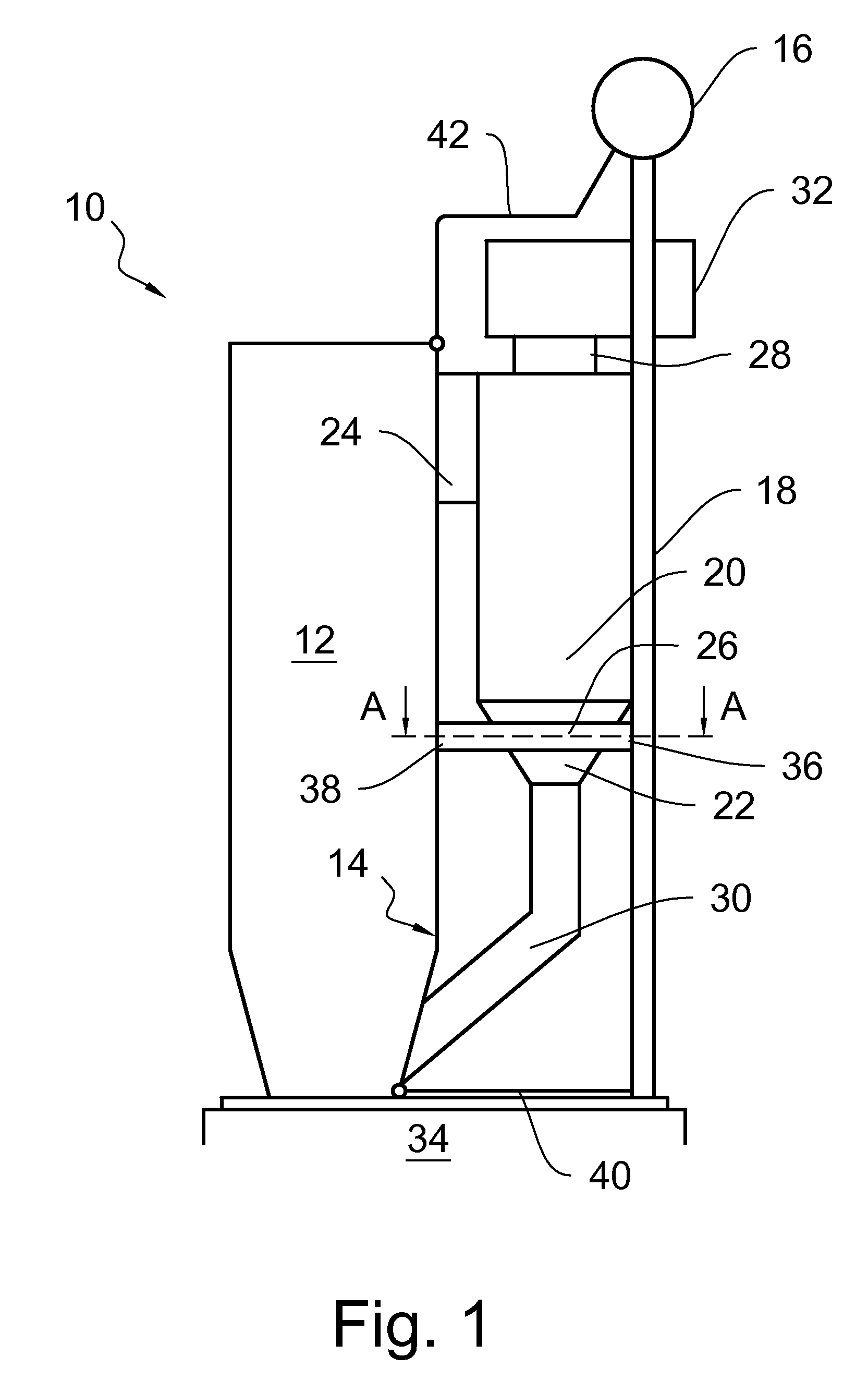
[0030]The schematic diagram of FIG. 1 illustrates a side view of a bottom-supported circulating fluidized bed boiler 10 arranged on a support foundation 34 made of, for example, concrete or steel. In the following description, it is assumed that thermal expansion of the boiler is entirely upwards, even if, in practice, there is also thermal expansion in the horizontal direction, which is generally taken into account by a suitable sliding support system.

[0031]The boiler 10 comprises a furnace 12 having a side wall 14, which may also be called a rear wall, a particle separator 20 located at the rear wall side of the furnace 12, a discharge conduit 24 for conveying flue gas and entrained particles from the upper portion of the furnace 12 to the particle separator 20, and conventional bottom-supported downcomer pipes 18 adjacent to an outer portion of the particle separator 20, in fluid connection with a steam drum 16. In practice, the boiler 10 also comprises other units, such as means...


PUM


Abstract

A fluidized bed boiler with a support construction for a particle separator. The fluidized bed boiler includes a bottom-supported furnace in which at least one particle separator with a support construction is in gas flow connection with an upper portion of the furnace and includes a furnace side portion, an outer portion opposite to the furnace side portion, and a conical lower portion. At least two bottom-supported downcomer pipes are in fluid connection with a steam drum and adjacent to the outer portion of the particle separator. The support construction includes a frame-like supporting member surrounding at least a portion of the conical lower portion, and an outboard portion of the supporting member is attached to the at least two downcomer pipes to support the at last one particle separator.

Description

CLAIM OF PRIORITY[0001]This application is a U.S. national stage application of PCT International Application No. PCT / FI2015 / 050364, filed May 27, 2015, which claims priority from Finnish patent application number 20145506, filed Jun. 3, 2014.BACKGROUND OF THE INVENTION[0002]1. Field of the Invention[0003]The present invention relates to a bottom-supported fluidized bed boiler with a support construction for a particle separator. More particularly, the invention relates to a fluidized bed boiler comprising a bottom-supported furnace, at least one particle separator with a support construction in gas flow connection with an upper portion of the furnace and comprising a furnace side portion, an outer portion opposite to the furnace side portion and a conical lower portion, and at least two bottom-supported downcomer pipes in fluid connection with a steam drum and adjacent to the outer portion of the particle separator.[0004]2. Description of Related Art[0005]Fluidized bed boilers comp...

Claims


Application Information

Patent Timeline
IPC IPC(8): F22B31/00F23C10/10F22B37/24
CPCF22B31/0015F23C10/10F22B37/24F22B31/0007F22B37/242F27B15/04F22B31/0084F22B37/207
Inventor LANKINEN, PENTTIHILTUNEN, VELI-MATTI
Owner SUMITOMO SHI FW ENERGIA OY
Why Eureka
Eureka Blog
Learn More