Self-Propelled Road Milling Machine

a road milling machine and self-propelled technology, which is applied in the direction of cutting machines, roads, roads, etc., can solve the problems of unavoidable wheel or running gears of the road milling machine, and achieve the effect of improving the milling resul

Active Publication Date: 2016-05-12
WIRTGEN GMBH
View PDF1 Cites 0 Cited by
  • Summary
  • Abstract
  • Description
  • Claims
  • Application Information

AI Technical Summary

Benefits of technology

[0008]Therefore, the object of the invention is to further improve the milling result when using a road milling machine, in particular a small miller.

Problems solved by technology

If the road surface is milled off in a plurality of adjacent milling sections, one of the wheels or running gears of the road milling machine unavoidably travels in a previously milled track, in which there may still be removed material.
In practice, it has been shown that this unevenness, even if only small, can be transferred to the subsequent milling track.
Although the known road milling machines generally have a device for compensating differences in height between the left-hand and right-hand wheels or running gears, which can be at different heights, for example in the previous milling track and on the road surface yet to be milled off, the known devices can compensate the small differences in height resulting from milling material lying in the milling track either only to an insufficient extent or not at all.

Method used


Image

  • Self-Propelled Road Milling Machine
  • Self-Propelled Road Milling Machine
  • Self-Propelled Road Milling Machine

Examples


Embodiment Construction

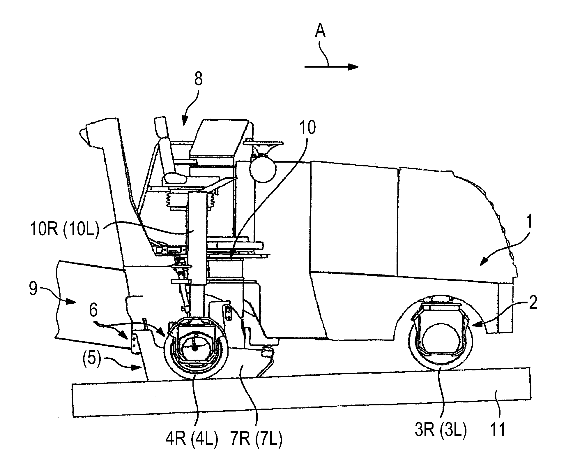
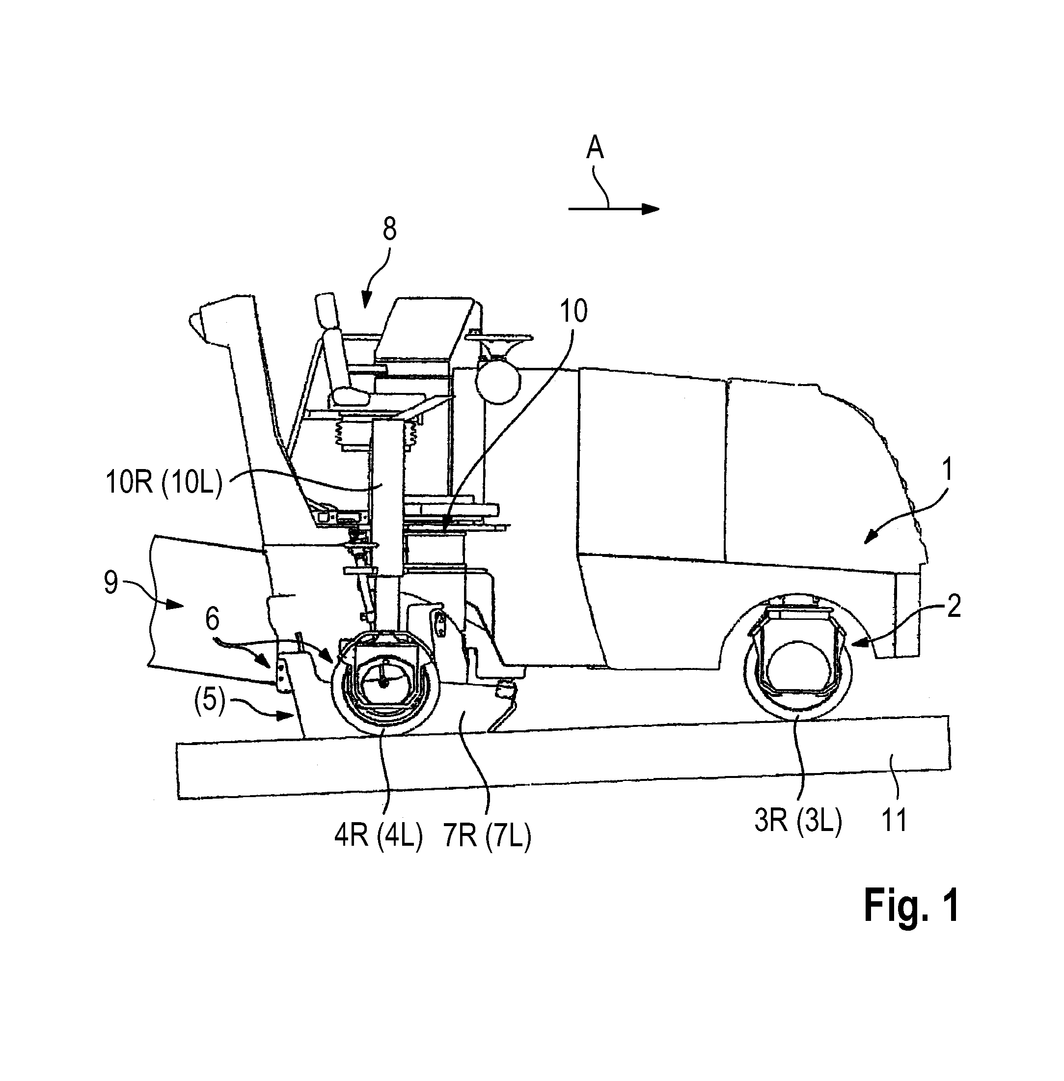
[0032]FIG. 1 is a side view of an embodiment of a road miller, in this case a small miller. The road miller comprises a machine frame 1 which is supported by a chassis 2. The chassis 2 comprises in the working direction A a front right-hand wheel 3R and a front left-hand wheel 3L and a rear right-hand wheel 4R and a rear left-hand wheel 4L. However, caterpillar tracks may also be provided in place of wheels. The wheels or caterpillar tracks may be referred to as ground engaging supports.

[0033]The road miller comprises a working device having a work roller (5) which is a milling roller equipped with milling tools. The milling roller (5) is arranged in a milling roller housing 6 which is closed by an edge protector 7R (7L) on both the left-hand and right-hand side in the working direction A. The operator's platform 8 is arranged above the milling roller housing 6. A transport device 9 (only shown in part) is arranged at the rear of the road miller, behind the milling roller (5) in the...


PUM


Abstract

The road milling machine according to the invention comprises a cleaning device which has a cleaning unit arranged in front of the work roller in the working direction. The cleaning unit ensures that the surface of the terrain over which the wheels or running gears travel is clear of material. As a result, an optimum milling result is always achieved. The invention takes effect in particular when using small millers which have at least one rear wheel or running gear which can be moved into an inner working position in relation to a longitudinal side of the machine frame and into an outer working position in relation to a longitudinal side of the machine frame. In this preferred embodiment, the cleaning device comprises a pivot device which is designed in such a way that the cleaning unit can be moved into an inner working position in relation to a longitudinal side of the machine frame and into an outer working position in relation to a longitudinal side of the machine frame. In the inner or outer working position, the cleaning unit is arranged on the same track as the rear wheel or running gear which can be moved into the inner or outer working position. This ensures that the track of the rear wheel or running gear is clear of milled material or other dirt, wherein the cleaning unit does not protrude too far beyond the rear wheel or running gear.

Description

BACKGROUND OF THE INVENTION[0001]1. Field of the Invention[0002]The invention relates to a self-propelled road milling machine which comprises a machine frame which is supported by a chassis and a working device having a work roller which comprises work tools, wherein the chassis of the road milling machine comprises two rear wheels or running gears and at least one front wheel or running gear.[0003]2. Description of the Prior Art[0004]A road milling machine having a milling roller arranged at the rear of the machine and a chassis which comprises two rear wheels and two front wheels is known from DE 196 31 042 A1 (U.S. Pat. No. 6,106,073A). The milling roller is arranged between the rear wheels. In the known road milling machine, one of the two rear wheels can be pivoted out of an outer position in relation to a longitudinal side of the machine frame, which position corresponds to the normal position, and into an inner position in relation to the longitudinal side of the machine fra...

Claims


Application Information

Patent Timeline
Patent Type & Authority Applications(United States)
IPC IPC(8): E01C23/088E01C23/12
CPCE01C23/127E01C23/088E01H1/053
Inventor BERNING, CHRISTIANBUNGARTEN, DIETERBUSLEY, PETERKLOFT, MARIUSBARIMANI, CYRUSHAHN, GUNTER
Owner WIRTGEN GMBH
Why Eureka
Try Eureka