Magnetic field measurement method and magnetic field measurement device

a magnetic field and measurement device technology, applied in the field of magnetic field measurement method of measuring magnetic field, can solve the problems of reducing the sensitivity of the magnetic field radiated by the measuring object, and the accuracy of the measuremen

Active Publication Date: 2016-05-12
SEIKO EPSON CORP
View PDF4 Cites 48 Cited by
  • Summary
  • Abstract
  • Description
  • Claims
  • Application Information

AI Technical Summary

Benefits of technology

[0030]According to these application examples, it is possible to provide a magnetic field measurement device capable of obtaining an original

Problems solved by technology

When the original magnetic field is present, sensitivity to a magnetic field radiated by a measuring

Method used


Image

  • Magnetic field measurement method and magnetic field measurement device
  • Magnetic field measurement method and magnetic field measurement device
  • Magnetic field measurement method and magnetic field measurement device

Examples


embodiment 1

Entire Configuration

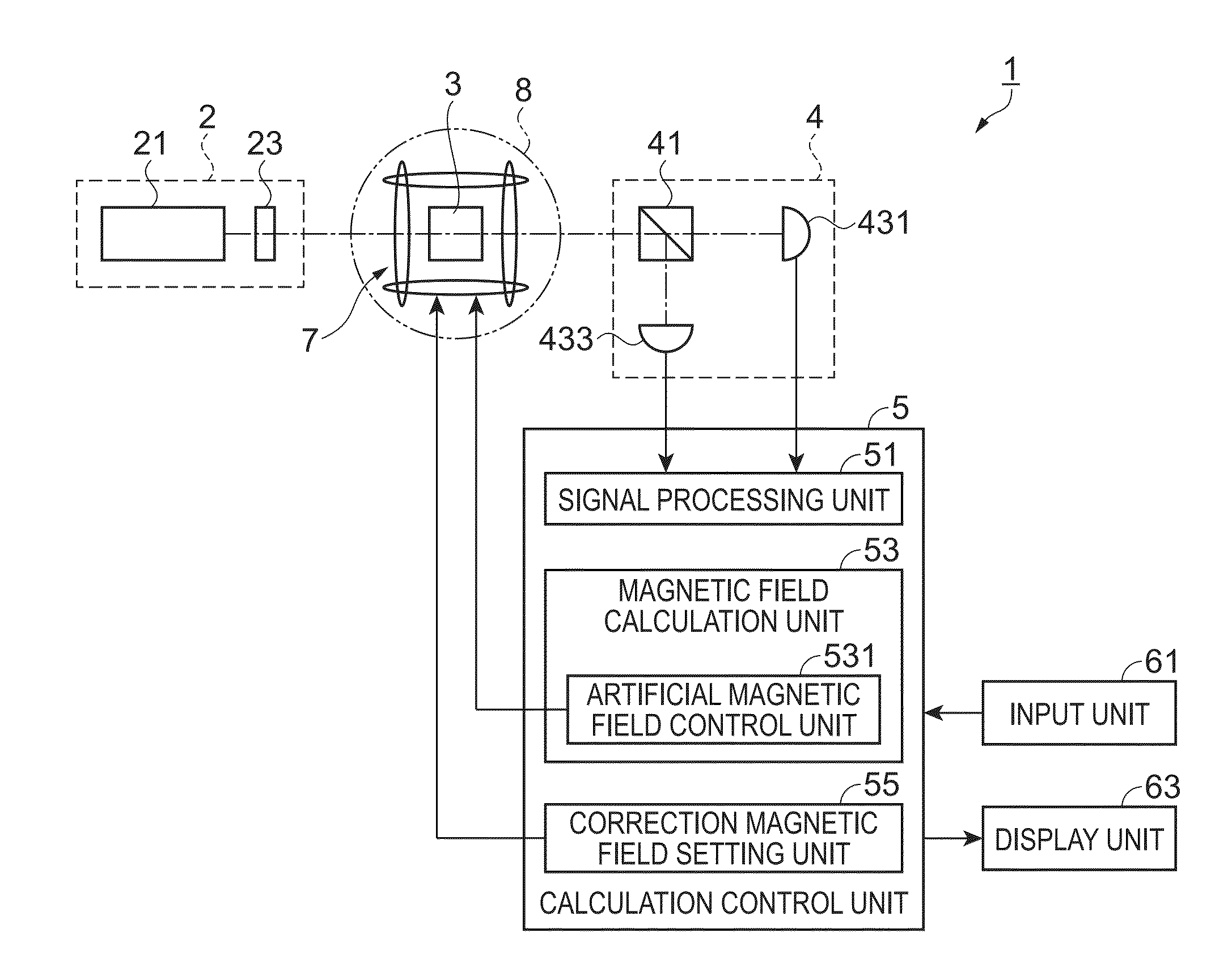
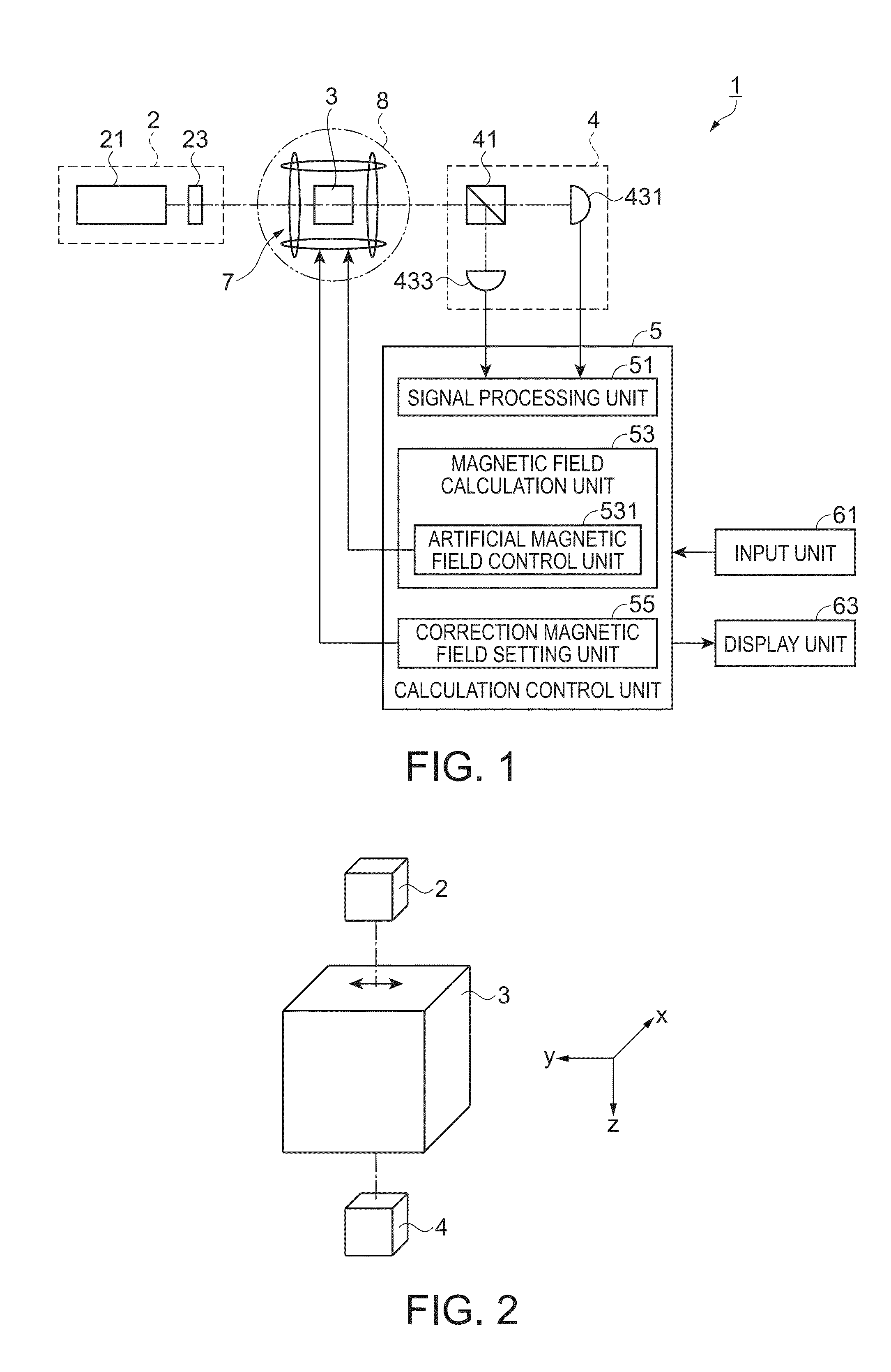
[0048]FIG. 1 is a diagram illustrating an entire configuration example of a magnetic field measurement device 1 of the present embodiment. In addition, FIG. 2 is a diagram illustrating an outline of an arrangement relation between a light source unit 2, a gas cell 3, and a polarimeter 4 constituting the magnetic field measurement device 1. The magnetic field measurement device 1 of the present embodiment is used in a magnetocardiograph that measures a magnetocardiogram or a magnetoencephalography that measures a magnetoencephalo. The magnetic field measurement device 1 has a so-called one-beam-type magnetic sensor incorporated therein which uses both pump light irradiation and probe light irradiation, as an optically-pumped magnetic sensor, and measures a magnetic field using nonlinear magneto-optical rotation (NMOR). Meanwhile, without being limited to a one-beam type, a so-called two-beam-type configuration may be used in which a light source unit that performs...

embodiment 2

[0087]In the aforementioned Embodiment 1, in a state where the y-axis component Ay is set to the fixed value Afy (for example, zero), a plurality of artificial magnetic fields A are generated by changing the x-axis component Ax and the z-axis component Az. On the other hand, in the present embodiment, in a state where the x-axis component Ax is set to the fixed value Afx (for example, zero), a plurality of artificial magnetic fields A may be generated by changing the y-axis component Ay and the z-axis component Az. The original magnetic field C=(Cx, Cy, Cz) may be calculated by the following Expressions (30) to (32) using the first magnetic field Ap=(Afx, Apy, Apz) when the square difference W− satisfies the maximum value condition and the second magnetic field Av=(Afx, Avy, Avz) when the square difference W− satisfies the minimum value condition in which a minimum value is set.

Cx=-Apy+Avy2-Afx(30)Cy=Apy-Avy2(31)Cz=-Apz+Avz2(32)

[0088]A method to obtain Expression (30) to Expression ...

embodiment 3

[0090]Next, a magnetic field measurement device of Embodiment 3 and a magnetic field measurement method using the device will be described with reference to FIGS. 11 to 15.

Entire Configuration

[0091]First, the magnetic field measurement device of the present embodiment will be described with reference to FIG. 11.

[0092]FIG. 11 is a diagram illustrating an entire configuration example of a magnetic field measurement device of Embodiment 3.

[0093]As shown in FIG. 11, a magnetic field measurement device 10 of the present embodiment has substantially the same configuration as that of the magnetic field measurement device 1 of the above Embodiment 1. The magnetic field calculation unit 53 of the calculation control unit 5 includes an amplitude detection unit 533 in addition to the artificial magnetic field control unit 531. Therefore, the same components as those of the magnetic field measurement device 1 of Embodiment 1 are denoted by the same reference numerals and signs, and thus the det...


PUM


Abstract

A light source unit irradiates a gas cell disposed in a measurement region with linearly polarized light in which the direction of travel is a z-axis direction and the vibration direction of an electric field is a y-axis direction. A polarimeter detects optical characteristics of light passing through the gas cell. A magnetic field generator applies an artificial magnetic field, capable of varying an x-axis component, a y-axis component, and a z-axis component, to the measurement region. A calculation control unit generates a plurality of artificial magnetic fields, calculates a magnetization value or a value corresponding to the magnetization value on the basis of the detection results of the polarimeter, and calculates an original magnetic field present in the measurement region, using an artificial magnetic field when the magnetization value or the value corresponding to the magnetization value satisfies a condition for external value.

Description

CROSS-REFERENCE TO RELATED APPLICATIONS[0001]The present application claims priority to Japanese Patent Applications JP 2014-229915, filed Nov. 12, 2014, JP 2014-229916, filed Nov. 12, 2014, JP 2015-107152, filed May 27, 2015 and JP 2015-107151, filed May 27, 2015, the entire disclosures of which are hereby incorporated by reference.BACKGROUND[0002]1. Technical Field[0003]Various embodiments of the present invention relate to a magnetic field measurement method of measuring a magnetic field, and the like.[0004]2. Related Art[0005]A device for measuring a weak magnetic field of a magnetic field (biomagnetic field) or the like, such as a magnetic field (magnetocardiogram) from the heart or a magnetic field (magnetoencephalo) from the brain, which is radiated by a living body is known in which an optically-pumped magnetic sensor that irradiates a gas cell having alkali metal atoms sealed therein with linearly polarized light and measures a magnetic field through the rotation of the pla...

Claims


Application Information

Patent Timeline
IPC IPC(8): G01R33/032G01R33/02
CPCG01R33/0206G01R33/0322A61B5/243A61B5/245G01R33/26
Inventor NAGASAKA, KIMIO
Owner SEIKO EPSON CORP
Why Eureka
Try Eureka