Fixing device and image forming apparatus

a technology of fixing device and fixing belt, which is applied in the direction of electrographic process apparatus, instruments, optics, etc., can solve the problems of deteriorating inability to efficiently heat the fixing belt, and achieve the effect of improving the temperature rise performance of the fixing bel

Active Publication Date: 2016-05-12
KYOCERA DOCUMENT SOLUTIONS INC
View PDF3 Cites 2 Cited by
  • Summary
  • Abstract
  • Description
  • Claims
  • Application Information

AI Technical Summary

Benefits of technology

[0011]The present invention makes it possible to improve the temperature rise performance of the fixing belt.

Problems solved by technology

Accompanying to this, it becomes impossible to efficiently heat the fixing belt and there is a concern that temperature rise performance of the fixing belt is deteriorated.

Method used


Image

  • Fixing device and image forming apparatus
  • Fixing device and image forming apparatus
  • Fixing device and image forming apparatus

Examples


Embodiment Construction

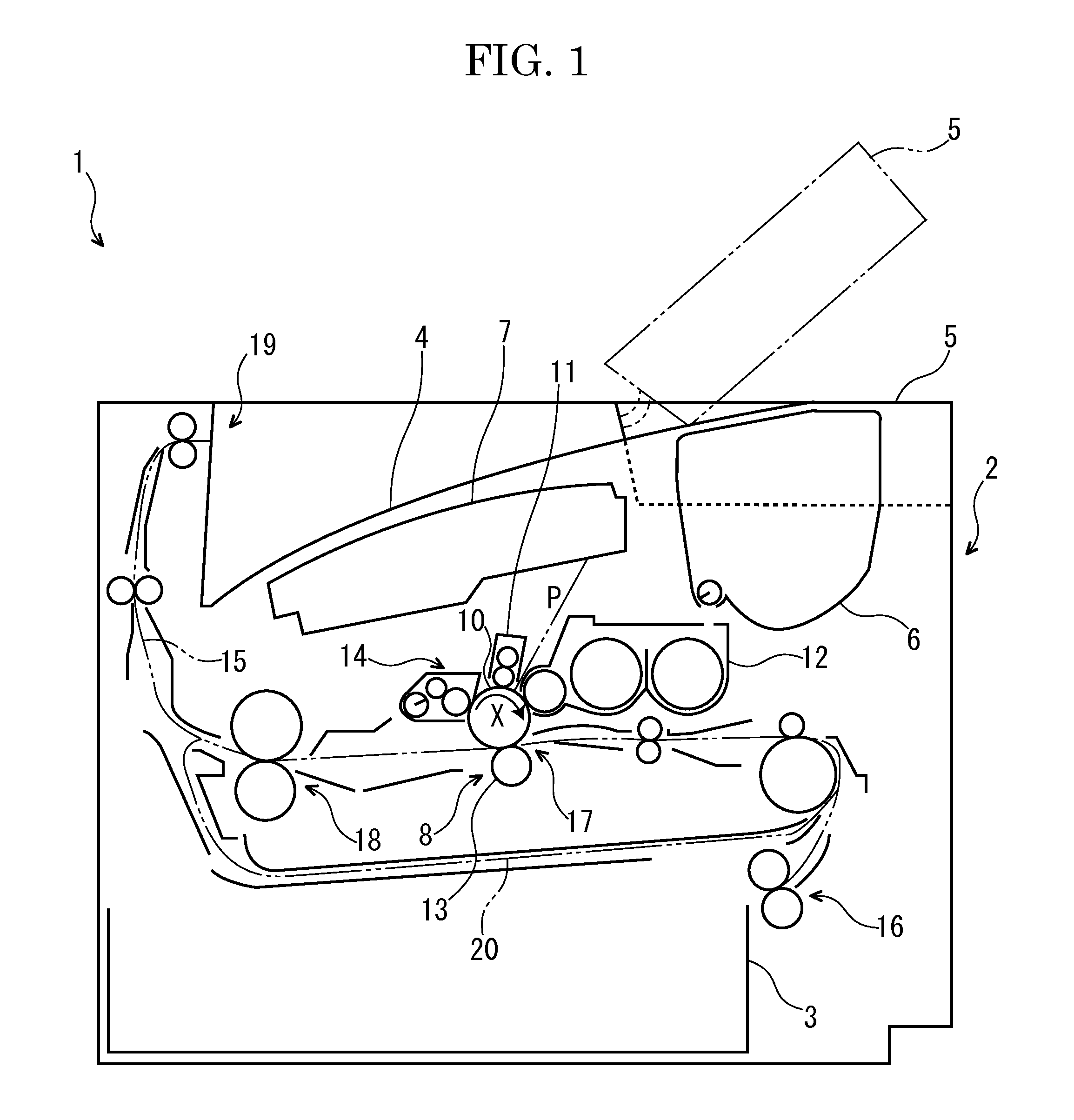
[0030]First, with reference to FIG. 1, the entire structure of a printer 1 (an image forming apparatus) will be described.

[0031]The printer 1 includes a box-like formed printer main body 2. In a lower part of the printer main body 2, a sheet feeding cartridge 3 storing sheets (recording mediums) is installed and, in a top face of the printer main body 2, an ejected sheet tray 4 is formed. To the top face of the printer main body 2, an upper cover 5 is openably / closably attached at a lateral side of the ejected sheet tray 4 and, below the upper cover 5, a toner container 6 is installed.

[0032]In an upper part of the printer main body 2, an exposure device 7 composed of a laser scanning unit (LSU) is located below the ejected sheet tray 4. Below the exposure device 7, an image forming part 8 is arranged. In the image forming part 8, a photosensitive drum 10 as an image carrier is rotatably arranged. Around the photosensitive drum 10, a charger 11, a development device 12, a transfer ro...


PUM


Abstract

A fixing device according to the present invention includes a fixing belt (22), a pressuring member (23), a heat source (24), a reflecting member (25) reflecting the radiant heat radiated from the heat source (24) to an inner circumference face of the fixing belt (22), a pressing member (27) pressing the fixing belt (22) to a side of the pressuring member (23) and a supporting member (26) supporting the pressing member (27). The reflecting member (25) is arranged between the heat source (24) and the supporting member (26) and configured to be curved or bent so as to project toward a side of the heat source (24). Straight lines (L) connecting a center (Z) of the heat source (24) with both end parts of the supporting member (26) in a conveying direction of a recording medium pass through the reflecting member (25).

Description

TECHNICAL FIELD[0001]The present invention relates to a fixing device configured to fix a toner image onto a recording medium and an image forming apparatus including the fixing device.BACKGROUND ART[0002]Conventionally, an electrographic image forming apparatus, such as a copying machine, a printer, a facsimile or a multifunction peripheral includes a fixing device configured to fix a toner image onto a recording medium, such as a sheet. For the fixing device, a heat roller manner is widely used. The heat roller manner is a manner to form a fixing nip by using a pair of rollers.[0003]On the other hand, a fixing manner is being shifted from the above-mentioned heat roller manner to a belt manner to reduce a heat capacity of the fixing device and to shorten a warm-up time. The belt manner is a manner to form a fixing nip by using a fixing belt.[0004]For example, Patent Document 1 discloses a fixing device including a fixing belt, a pressuring member (see “pressuring roller 22” of Pat...

Claims


Application Information

Patent Timeline
Patent Type & Authority Applications(United States)
IPC IPC(8): G03G15/20
CPCG03G15/2007G03G15/2053G03G15/206G03G2215/2035
Inventor YAMAGISHI, YOSHIHIROKANEMATSU, YOSHIHARU
Owner KYOCERA DOCUMENT SOLUTIONS INC
Why Eureka
Try Eureka