Eureka AIR delivers breakthrough ideas for toughest innovation challenges, trusted by R&D personnel around the world.

Display apparatus

Inactive Publication Date: 2016-05-12
SAMSUNG DISPLAY CO LTD
View PDF3 Cites 6 Cited by
  • Summary
  • Abstract
  • Description
  • Claims
  • Application Information

AI Technical Summary

Benefits of technology

The invention relates to improving the quality of images displayed on LCD panels. The patent discusses a problem with LCD panels having a peripheral area around the display area where the gate and data driving parts are located. This peripheral area can affect the display quality and cause a boundary area to appear dark or gray when multiple LCD panels are connected. The invention proposes a solution by applying a different gate signal to at least one sub-area of the display area, which removes the luminance difference and ensures consistent display quality across the entire panel. Additionally, the invention suggests gradually changing the capacitance of the display area and connecting a new gate extension line to remove the luminance difference in the boundary area between panels.

Problems solved by technology

However, a sharp variation of kick-back voltage across the sub-areas may occur and a difference of luminance may be observed, deteriorating the display quality of the LCD display device.

Method used


Image

  • Display apparatus
  • Display apparatus
  • Display apparatus

Examples


Embodiment Construction

[0049]Hereinafter, the inventive concept will be explained in detail with reference to the accompanying drawings.

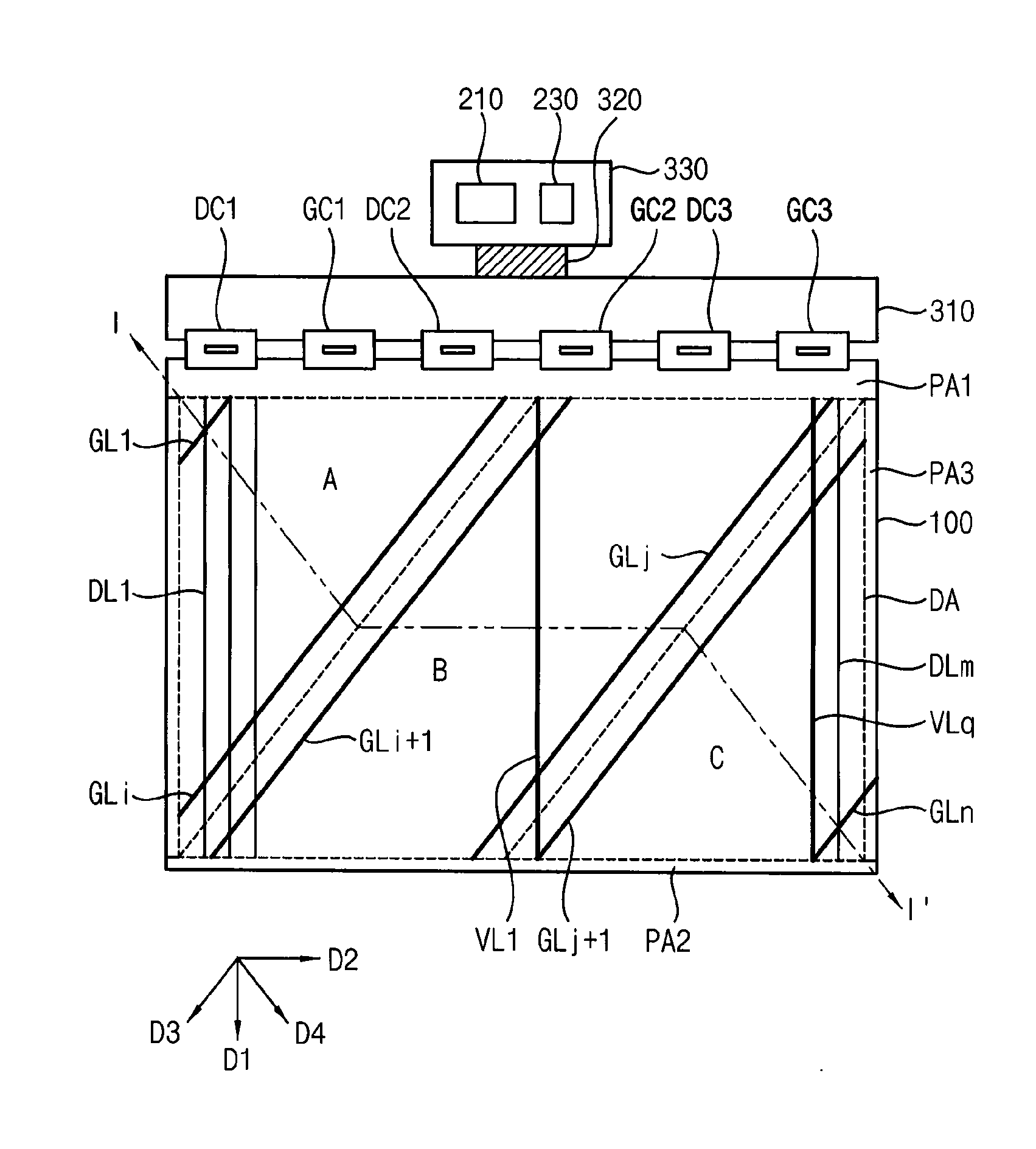
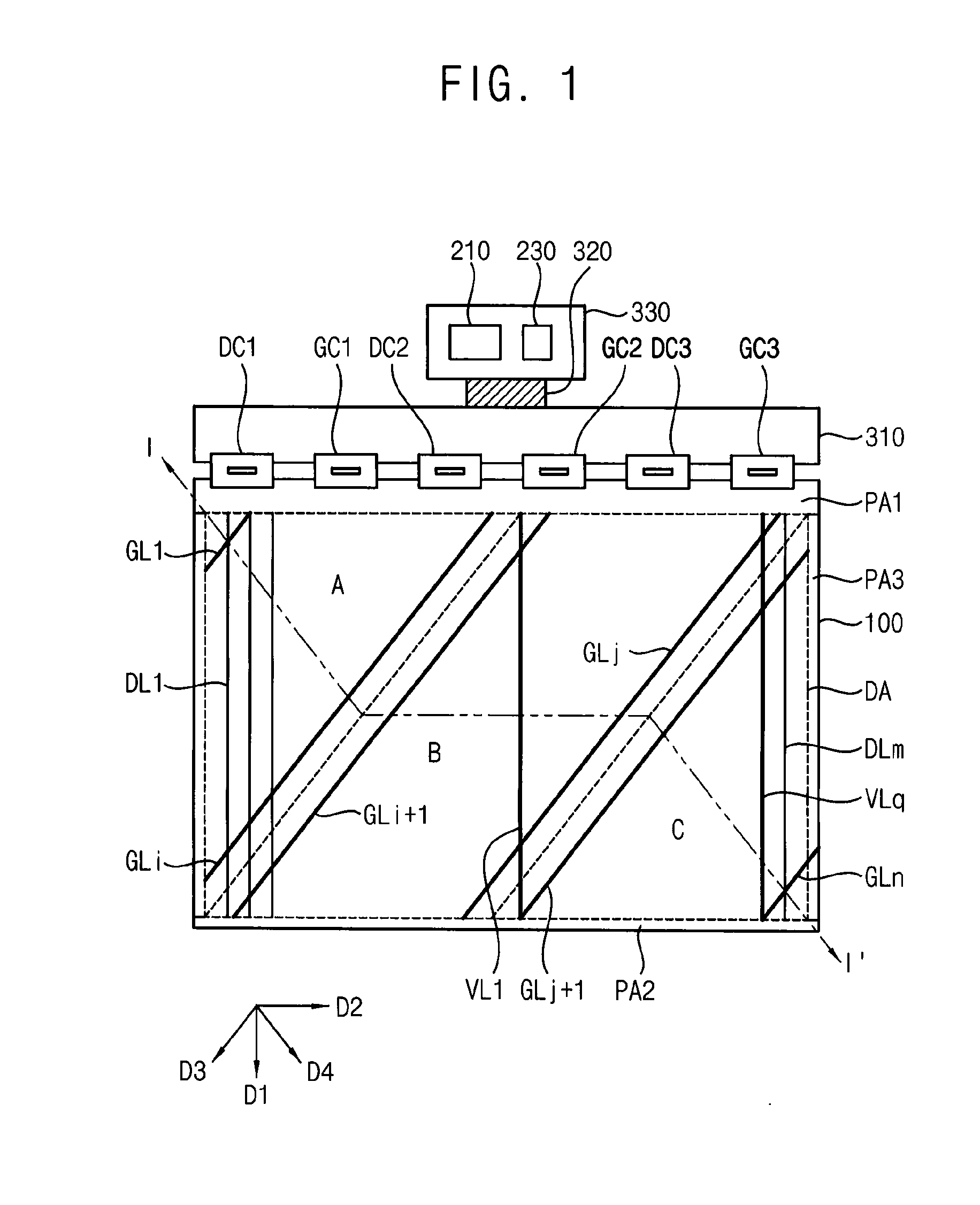
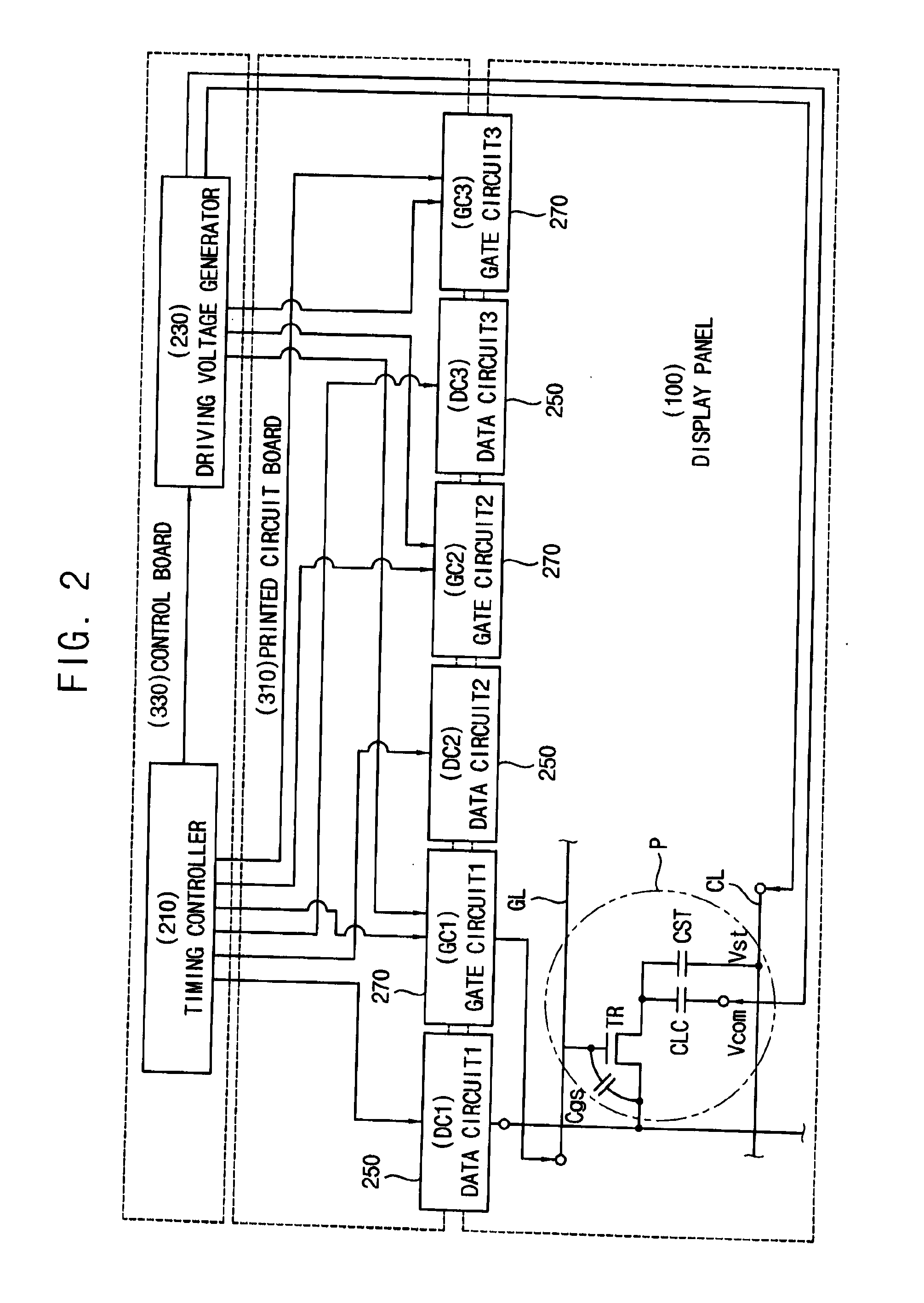
[0050]FIG. 1 is a plan view illustrating a display apparatus according to an exemplary embodiment. FIG. 2 is a block diagram illustrating a timing controller of FIG. 1.

[0051]Referring to FIGS. 1 and 2, the display apparatus may include a display panel 100, a timing controller 210, a driving voltage generator 230, a data driver 250 and a gate driver 270.

[0052]The display panel 100 may include a display area DA displaying an image and a plurality of peripheral areas PA1 to PA4 surrounding the display area DA. The data driver 250 and the gate driver 270 are disposed in a first peripheral area PA1 of the peripheral areas.

[0053]The data driver 250 may include a plurality of data circuits DC1, DC2 and DC3. The gate driver 270 may include a plurality of gate circuits GC1, GC2 and GC3 which are disposed in the first peripheral area PA1 in which the data circuits DC1, DC2 and DC3 ...


PUM


Abstract

A display apparatus includes a display panel comprising a plurality of gate lines extending in a first diagonal direction of a display area, and a plurality of vertical lines extending in a vertical direction, the gate lines comprising a plurality of first gate lines disposed in a first sub-area of the display area, a plurality of second gate lines disposed in a second sub-area of the display area, a plurality of third gate lines disposed in a third sub-area of the display area, the third gate lines respectively connected to the vertical lines, and a gate driver disposed in the first peripheral area in which the data driver is disposed and configured to provide at least one of the first, second and third sub-areas with a gate signal different from a reference gate signal.

Description

CLAIM OF PRIORITY[0001]This application claims the priority from and all the benefits accruing under 35 U.S.C. §119 of Korean Patent Application No. 10-2014-0154697, filed on Nov. 7, 2014 in the Korean Intellectual Property Office (“KIPO”), which is hereby incorporated by reference for all purposes as if fully set forth herein.BACKGROUND OF THE INVENTION[0002]1. Field of the Invention[0003]Exemplary embodiments of the inventive concept relate to a display apparatus. More particularly, example embodiments of the inventive concept relate to a display apparatus for improving a display quality.[0004]2. Description of the Related Art[0005]Generally, a liquid crystal display (LCD) apparatus has a relatively small thickness, low weight and low power consumption. Thus the LCD apparatus is used in monitors, laptop computers and cellular phones, etc. The LCD apparatus includes an LCD panel displaying images using a selectively changeable light transmittance characteristic of a liquid crystal ...

Claims


Application Information

Patent Timeline
IPC IPC(8): G09G3/36G09G5/18
CPCG09G5/18G09G3/3696G09G3/3677G09G2320/0219
Inventor SONG, HEE-RIMJUNG, KWANG-CHULKIM, IL-GONSONG, SE-YOUNG
Owner SAMSUNG DISPLAY CO LTD
Why Eureka
Eureka Blog
Learn More