Tool for insertion into a surgical saw, and method for milling a groove

a surgical saw and tool technology, applied in the field of surgical saw tools, can solve the problems of high operation cost and increase the variance of bone groove dimensions, and achieve the effect of improving the surface created by the tool in the bone groove and ensuring the tooth shap

Active Publication Date: 2016-05-19
RENG WOLFGANG
View PDF6 Cites 1 Cited by
  • Summary
  • Abstract
  • Description
  • Claims
  • Application Information

AI Technical Summary

Benefits of technology

The invention is a tool used for shaping bone during surgery. Unlike conventional saw blades, the tool presses bone particles onto the bone, making the bone material more durable and load-bearing. The tool has lateral surfaces that allow for good compacting of the bone material on the groove's lateral surface. This results in an increased stability of the bone material and improved durability of the implant. The head of the tool has planar lateral surfaces that run parallel to the work direction.

Problems solved by technology

The freehand preparation of the groove with the special chisel can consequently lead to an increased variance in the bone groove dimensions.
The known tool is, in addition, only permitted for one-time use, so that for each operation a new saw tool is necessary and thereby high operation costs arise.

Method used


Image

  • Tool for insertion into a surgical saw, and method for milling a groove
  • Tool for insertion into a surgical saw, and method for milling a groove
  • Tool for insertion into a surgical saw, and method for milling a groove

Examples


Embodiment Construction

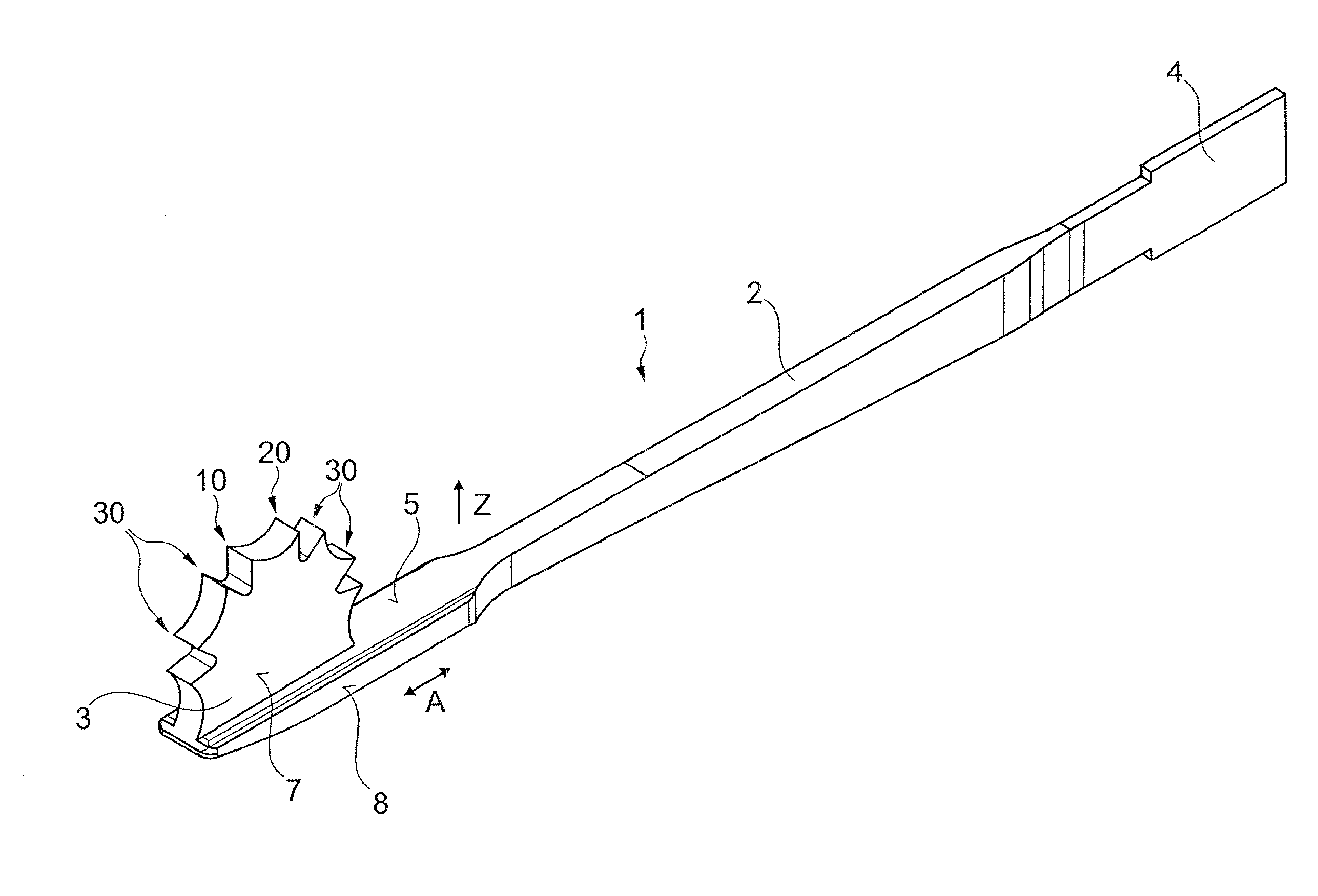
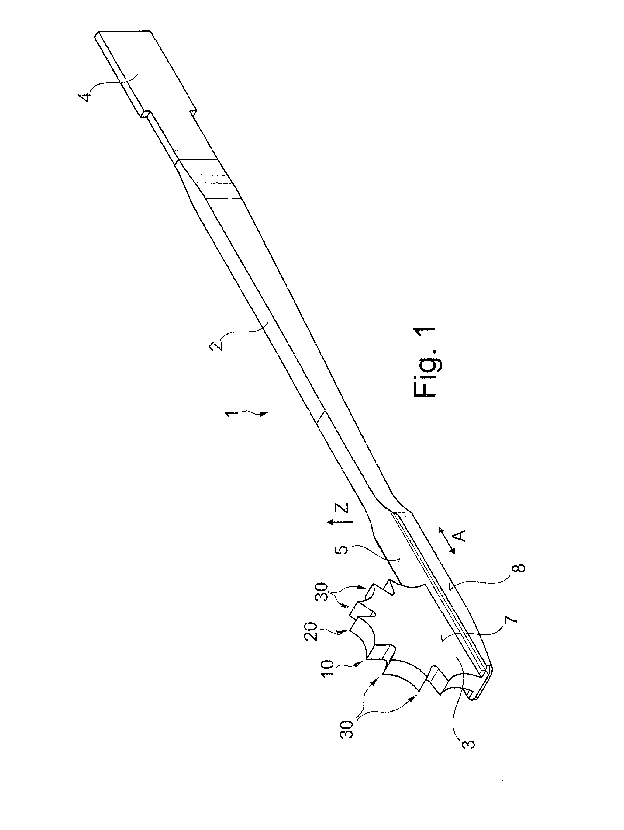
[0031]In FIG. 1 a tool 1 for insertion into a surgical jigsaw is illustrated. The tool 1 has an elongated body 2 with a longitudinal direction. A head 3 is arranged at a first end of the body 2. At a second end of the body 2, a holder area 4 is arranged, which is adapted to a tool holder of the surgical jigsaw. The tool 1 is inserted with the holder area 4 into the tool holder of the surgical jigsaw and, when the surgical jigsaw is switched on, is moved forward and backward by the surgical jigsaw parallel to the longitudinal direction of the body 2. The direction of the oscillating movement of the tool 1 is indicated in FIG. 1 by the double arrow marked by the letter A and is designated as the work direction. The head 3 has a first tooth 10 and a second tooth 20 for milling off bone material. The configuration of the teeth 10 and 20 is explained in further detail below. In addition to the teeth 10 and 20, the head 3 can have further teeth 30, which are configured in a similar manner...


PUM


Abstract

A tool for insertion into a surgical saw includes a holder area for the saw and a head which is movable in oscillation by the surgical saw along a work direction where the head has a plurality of teeth which are arranged behind one another in the work direction. A first and second tooth each contains a first shaving surface for shaving off bone material oriented transversely to the work direction and a second pressing surface for pressing on bone material which pressing surface adjoins the shaving surface. The shaving surface, in relation to the work direction, is more inclined than the pressing surface. The two teeth are oriented with their shaving surface and pressing surface opposite each other so during oscillation the shaving surface of the tooth lying ahead in work direction and the pressing surface of the tooth lying therebehind in work direction are in operation.

Description

CROSS-REFERENCE TO RELATED APPLICATIONS[0001]This continuation application claims priority to PCT / EP2014 / 064312 filed on Jul. 4, 2014 which has been published as WO 2015 / 007546 A1 and also the German patent number 10 2013 107 485 filed on Jul. 15, 2013, the contents of which are fully incorporated herein with these references.FIELD OF THE INVENTION[0002]The invention relates to a tool for insertion into a surgical saw. A tool for insertion into a surgical saw with a holder area adapted to a tool holder of the surgical saw and with a head which is movable in oscillation by the surgical saw along a work direction and has a plurality of teeth which are arranged behind one another in the work direction, is known from U.S. Pat. No. D622,383 S and U.S. Pat. No. D622,386 S. The known tool has at its head two parallel saw blades with a plurality of teeth being off-set with respect to one another. The two saw blades are arranged at a distance from one another, so that two parallel slots can ...

Claims


Application Information

Patent Timeline
Patent Type & Authority Applications(United States)
IPC IPC(8): A61B17/14
CPCA61B17/148A61B17/141
Inventor RENG, WOLFGANG
Owner RENG WOLFGANG
Why Eureka
Try Eureka