Method of driving touch panel, capacitance-type touch panel, and display apparatus with touch detection function

a technology of capacitance-type touch panel and display apparatus, applied in the field of touch panel, can solve the problems of complex circuit configuration, large selection time, and high cost, and achieve the effects of reducing disturbance noise, simplifying detection circuit, and removing folding nois

Active Publication Date: 2016-05-19
JAPAN DISPLAY INC
View PDF0 Cites 14 Cited by
  • Summary
  • Abstract
  • Description
  • Claims
  • Application Information

AI Technical Summary

Benefits of technology

[0009]As another method of removing the disturbance noise, a generally-known noise filter is considered to be used. For example, a low-pass filter having a cutoff frequency lower than the relevant Nyquist frequency is inserted before A / D conversion, thereby folding noise may be removed. Thus, the disturbance noise may be removed, and a detection circuit may be simplified after A / D conversion. However, a touch signal in synchronization with a drive signal outputted from a touch panel is a positive-negative symmetrical polarity-alternating signal and therefore may not pass through the low-pass filter. Specifically, the low-pass filter removes not only the disturbance noise but also the touch signal.
[0010]It is desirable to provide a method of driving a touch panel, in which presence of touch may be securely detected while influence of the disturbance noise and touch detection time are reduced despite using a relatively simple circuit configuration, and provide a touch panel and a display apparatus with a touch detection function using the drive method each.
[0019]According to the method of driving a touch panel, the capacitance-type touch panel, and the display device with a touch detection function of the embodiment of the invention, when an external proximity object exists, a touch component included in a detection signal from a touch detection electrode has positive-negative asymmetry, therefore even if signal processing of a detection signal is performed via an analog filter for noise removal, the touch component is not removed from the detection signal. Therefore, the touch signal may be securely detected while removing disturbance noise. Moreover, since processing of sequentially changing frequency of a drive signal to select a detection condition is unnecessary unlike in the past, reduction in size of a detection circuit and decrease in detection time may be achieved.

Problems solved by technology

However, in the drive method of the capacitance-type touch panel and the detection method thereof disclosed in the above-mentioned United States patent application Publication, since a frequency of a drive signal needs to be sequentially changed to select a condition at which a touch signal is hardly affected by disturbance noise, much time may be taken for selecting the condition.
Furthermore, preparation of drive signals having a plurality of frequencies is necessary, and switching timing of the signals needs to be determined, so that a circuit configuration may be complicated and large.
However, a touch signal in synchronization with a drive signal outputted from a touch panel is a positive-negative symmetrical polarity-alternating signal and therefore may not pass through the low-pass filter.

Method used


Image

  • Method of driving touch panel, capacitance-type touch panel, and display apparatus with touch detection function
  • Method of driving touch panel, capacitance-type touch panel, and display apparatus with touch detection function
  • Method of driving touch panel, capacitance-type touch panel, and display apparatus with touch detection function

Examples


first embodiment

2. First Embodiment

Configuration Example

General Configuration Example

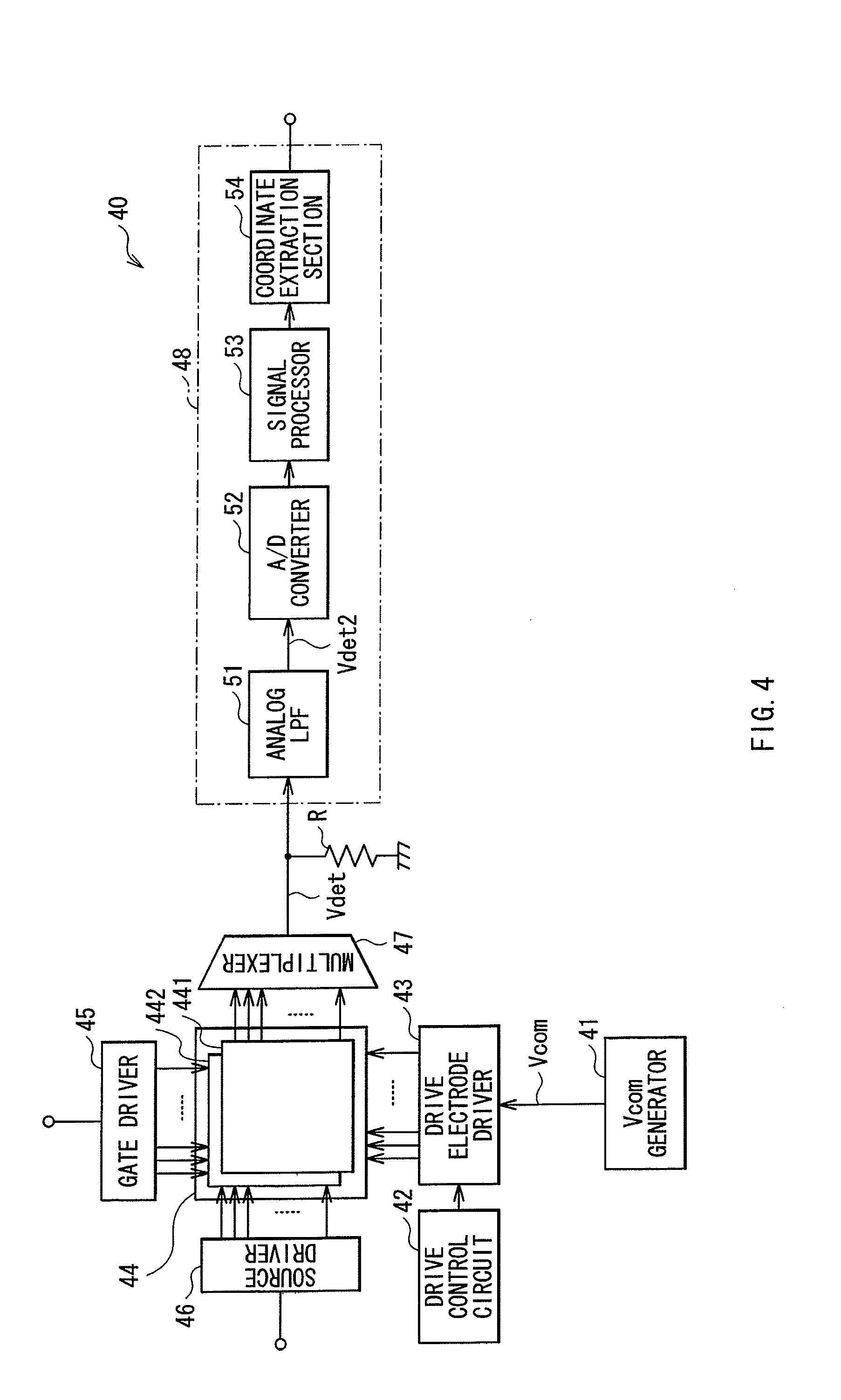
[0055]FIG. 4 shows a configuration example of a display apparatus with a touch detection function according to a first embodiment of the invention. Since a method of driving a touch panel according to an embodiment of the invention is embodied by the embodiment, the method is described together. The display apparatus is a so-called in-cell type apparatus where liquid crystal display elements are used as display elements, and besides, a liquid crystal display device configured of the liquid crystal display elements is integrated with a capacitance-type touch sensor.

[0056]The display apparatus with a touch detection function 40 includes a Vcom generator 41, a drive control circuit 42, a drive electrode driver 43, a display device with a touch detection function 44, a gate driver 45, a source driver 46, a multiplexer 47, a detection circuit 48, and a resistance R.

[0057]The Vcom generator 41 is a circuit generating a d...

modification 1-1

[0114]In the embodiment, when a voltage of the drive signal Vcom is positive (high level), the detection drive line group L1P is selected as in FIG. 8A, and when the voltage is negative (low level), the detection drive line group L1N is selected as in FIG. 8B. However, opposite setting may be used. Specifically, it may be designed that when a voltage of the drive signal Vcom is negative (low level), a detection drive line group is selected as in FIG. 8A, and when the voltage is positive (high level), a detection drive line group is selected as in FIG. 8B.

modification 1-2

[0115]In the embodiment, when a voltage of the drive signal Vcom is negative, the detection drive line group L1N is configured of drive electrodes discretely arranged on the whole surface of the touch sensor 441. However, this is not limitative, and may be appropriately modified as long as the following condition is satisfied: wherever a proximity object such as a finger is on the touch sensor 441, width (number of drive electrodes) of a strip region overlapping with the proximity object in the detection drive line group L1N is smaller than width (number of drive electrodes) of a strip region overlapping with the proximity object in the detection drive line group UP. For example, as shown in FIGS. 13A and 13B, when a voltage of the drive signal Vcom is negative (low level), the drive electrodes of the detection drive line group L1N may be discretely located only in an upper-half region of the touch sensor 441. Alternatively, for example, as shown in FIGS. 14A and 14B, thin strip ele...


PUM


Abstract

A capacitance-type touch panel, allowing disturbance noise and touch detection time to be reduced and having a simple configuration, is provided. The capacitance-type touch panel including: a plurality of drive electrodes each having a strip shape; a drive control circuit performing control such that a drive signal for touch detection is selectively applied to the drive electrodes; a plurality of touch detection electrodes arranged to intersect with the drive electrodes in such a manner that capacitance is formed in each intersecting part, and each outputting a detection signal in synchronization with the drive signal; and a detection circuit detecting an external proximity object based on the detection signal. The drive control circuit controls application of the drive signal in such a manner that the detection signal is a polarity-alternating signal including a positive-negative asymmetrical signal component which is due to presence of the external proximity object.

Description

CROSS REFERENCES TO RELATED APPLICATIONS[0001]The subject matter of application Ser. No. 12 / 794,289 is incorporated herein by reference. The present application is a Continuation of U.S. Ser. No. 12 / 794,289, filed Jun. 4, 2010, which claims priority to Japanese Patent Application No. JP2009-154207 filed in the Japanese Patent Office on Jun. 29, 2009, the entire content of which is hereby incorporated by reference.BACKGROUND OF THE INVENTION[0002]1. Field of the Invention[0003]The present invention relates to a touch panel that may be inputted with information by contact or approach of a user with a finger or the like, and particularly relates to a method of driving a touch panel detecting touch based on change in capacitance, and a touch panel and a display apparatus with a touch detection function using the method each.[0004]2. Description of Related Art[0005]A display device is recently noticed, in which a contact detector, so-called touch panel, is mounted on a display device suc...

Claims


Application Information

Patent Timeline
Patent Type & Authority Applications(United States)
IPC IPC(8): G06F3/041G09G3/36G06F3/047G06F3/044
CPCG06F3/0416G06F3/044G06F3/0412G09G2310/06G09G3/3696G06F3/047G09G3/3614G02F1/13338G06F3/04166G06F3/04184G06F3/0445G06F3/0446
Inventor NOGUCHI, KOUJIHARADA, TSUTOMUKIDA, YOSHITOSHINAKANISHI, TAKAYUKIISHIZAKI, KOJITAKEUCHI, TAKEYA
Owner JAPAN DISPLAY INC
Why Eureka
Try Eureka