Method of driving touch panel, capacitance-type touch panel, and display apparatus with touch detection function
a technology of capacitance-type touch panel and display apparatus, applied in the field of touch panel, can solve the problems of complex circuit configuration, large selection time, and high cost, and achieve the effects of reducing disturbance noise, simplifying detection circuit, and removing folding nois
- Summary
- Abstract
- Description
- Claims
- Application Information
AI Technical Summary
Benefits of technology
Problems solved by technology
Method used
Image
Examples
first embodiment
2. First Embodiment
Configuration Example
General Configuration Example
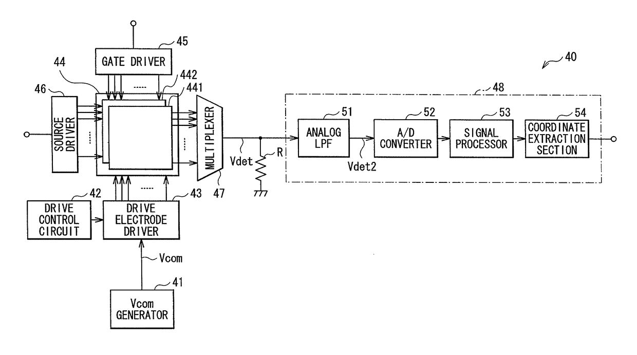
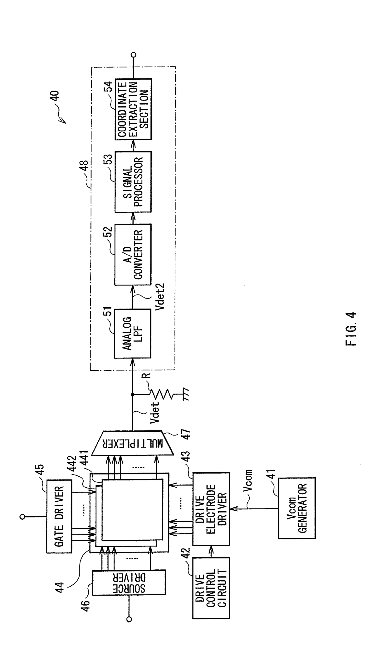
[0055]FIG. 4 shows a configuration example of a display apparatus with a touch detection function according to a first embodiment of the invention. Since a method of driving a touch panel according to an embodiment of the invention is embodied by the embodiment, the method is described together. The display apparatus is a so-called in-cell type apparatus where liquid crystal display elements are used as display elements, and besides, a liquid crystal display device configured of the liquid crystal display elements is integrated with a capacitance-type touch sensor.
[0056]The display apparatus with a touch detection function 40 includes a Vcom generator 41, a drive control circuit 42, a drive electrode driver 43, a display device with a touch detection function 44, a gate driver 45, a source driver 46, a multiplexer 47, a detection circuit 48, and a resistance R.
[0057]The Vcom generator 41 is a circuit generating a d...
modification 1-1
[0114]In the embodiment, when a voltage of the drive signal Vcom is positive (high level), the detection drive line group L1P is selected as in FIG. 8A, and when the voltage is negative (low level), the detection drive line group L1N is selected as in FIG. 8B. However, opposite setting may be used. Specifically, it may be designed that when a voltage of the drive signal Vcom is negative (low level), a detection drive line group is selected as in FIG. 8A, and when the voltage is positive (high level), a detection drive line group is selected as in FIG. 8B.
modification 1-2
[0115]In the embodiment, when a voltage of the drive signal Vcom is negative, the detection drive line group L1N is configured of drive electrodes discretely arranged on the whole surface of the touch sensor 441. However, this is not limitative, and may be appropriately modified as long as the following condition is satisfied: wherever a proximity object such as a finger is on the touch sensor 441, width (number of drive electrodes) of a strip region overlapping with the proximity object in the detection drive line group L1N is smaller than width (number of drive electrodes) of a strip region overlapping with the proximity object in the detection drive line group UP. For example, as shown in FIGS. 13A and 13B, when a voltage of the drive signal Vcom is negative (low level), the drive electrodes of the detection drive line group L1N may be discretely located only in an upper-half region of the touch sensor 441. Alternatively, for example, as shown in FIGS. 14A and 14B, thin strip ele...
PUM
| Property | Measurement | Unit |
|---|---|---|
| frequency | aaaaa | aaaaa |
| capacitance | aaaaa | aaaaa |
| surface area | aaaaa | aaaaa |
Abstract
Description
Claims
Application Information
 - R&D
- Intellectual Property
- Life Sciences
- Materials
- Tech Scout
- Unparalleled Data Quality
- Higher Quality Content
- 60% Fewer Hallucinations
Browse by: Latest US Patents, China's latest patents, Technical Efficacy Thesaurus, Application Domain, Technology Topic, Popular Technical Reports.
© 2025 PatSnap. All rights reserved.Legal|Privacy policy|Modern Slavery Act Transparency Statement|Sitemap|About US| Contact US: help@patsnap.com


