
Image processing apparatus and image processing method

Active Publication Date: 2016-05-19
CANON KK
View PDF3 Cites 1 Cited by
  • Summary
  • Abstract
  • Description
  • Claims
  • Application Information

AI Technical Summary

Benefits of technology

The present invention allows for priority to be assigned to threads based on their load level, which helps to prevent changes in load level. This results in the need for less memory space when performing high-speed processes, and helps to avoid the need for a spooler.

Problems solved by technology

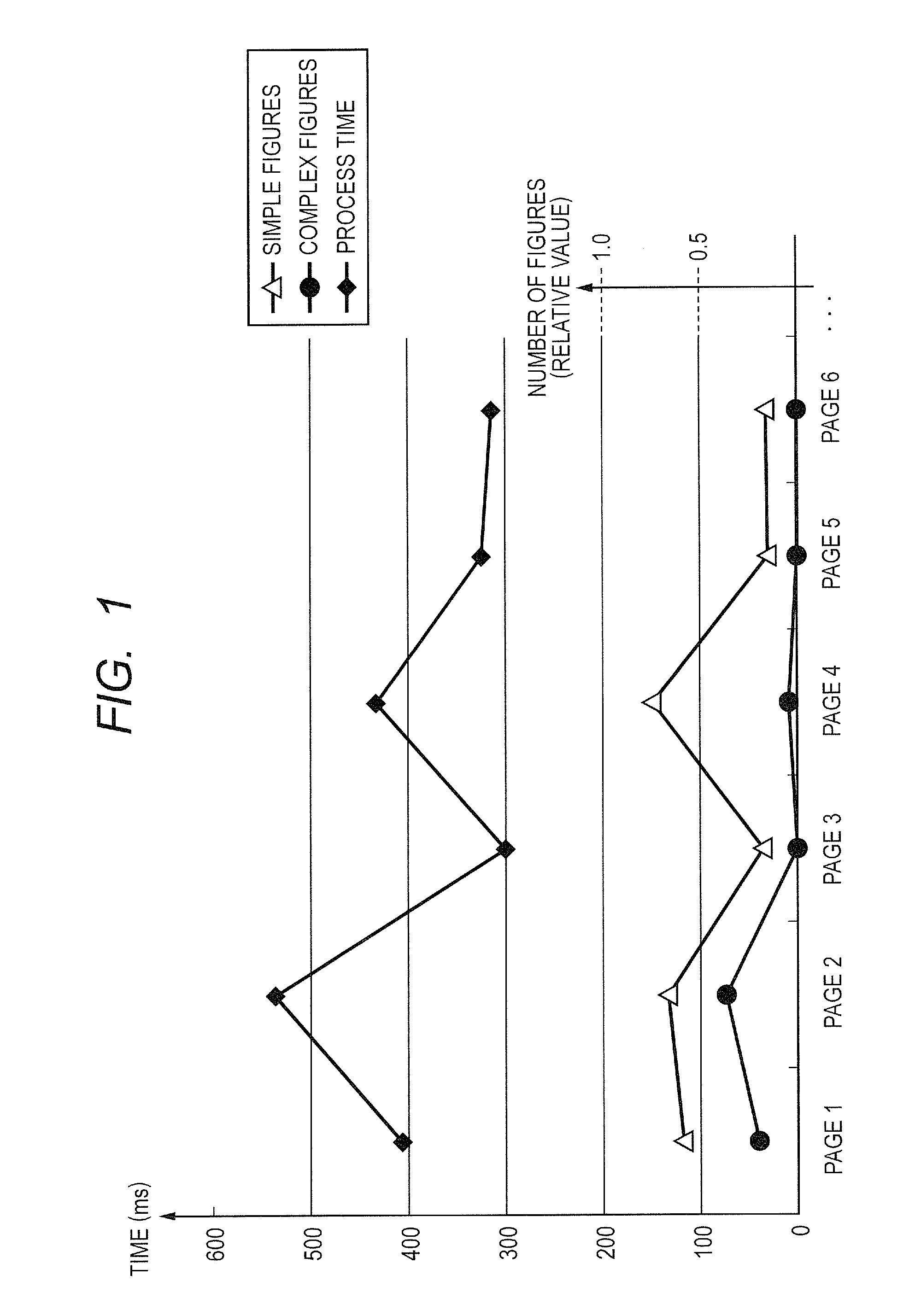
However, since time actually required for the rendering process changes depending on kinds and the number of figures, it is not easy to achieve the high-speed drawing process.
In a print system including the image processing apparatus, when the printer engine is started and thus printing is once started, the printer engine cannot easily be stopped.
However, the increase of the memory size is directly linked to the increase of the costs for the image processing apparatus.
However, in case of actually trying to change over the processes based on such a predicted value, it can be understood that the prediction itself for process speed is not easy.
Besides, when the individual data are compared, it can be read that it is not easy to directly use the individual data for predicting the process time.
That is, when the control is performed according to the result of the prediction of which the accuracy is not high, a large-sized memory is necessary for the spooler, so that the costs inevitably increase.
In other words, since the spooler capacity has been determined experientially or experimentally in the conventional image processing apparatus, the waste costs have occurred without any analysis and devisal for the capacity reduction.

Method used


Image

  • Image processing apparatus and image processing method
  • Image processing apparatus and image processing method
  • Image processing apparatus and image processing method

Examples


first embodiment

[0045]Initially, the first embodiment will be described. Here, FIG. 5 is a block diagram illustrating a function constitution of an image processing apparatus according to the first embodiment.

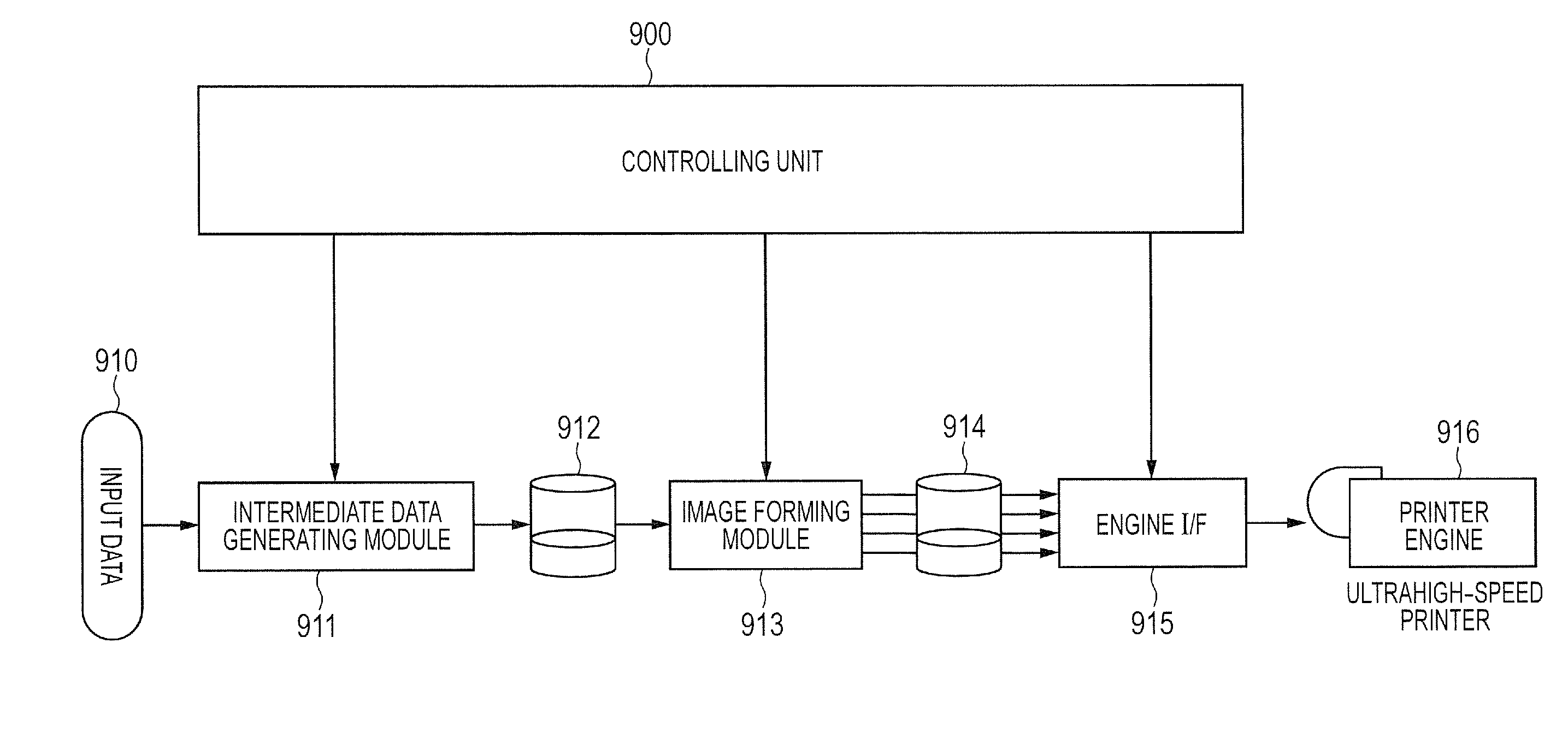
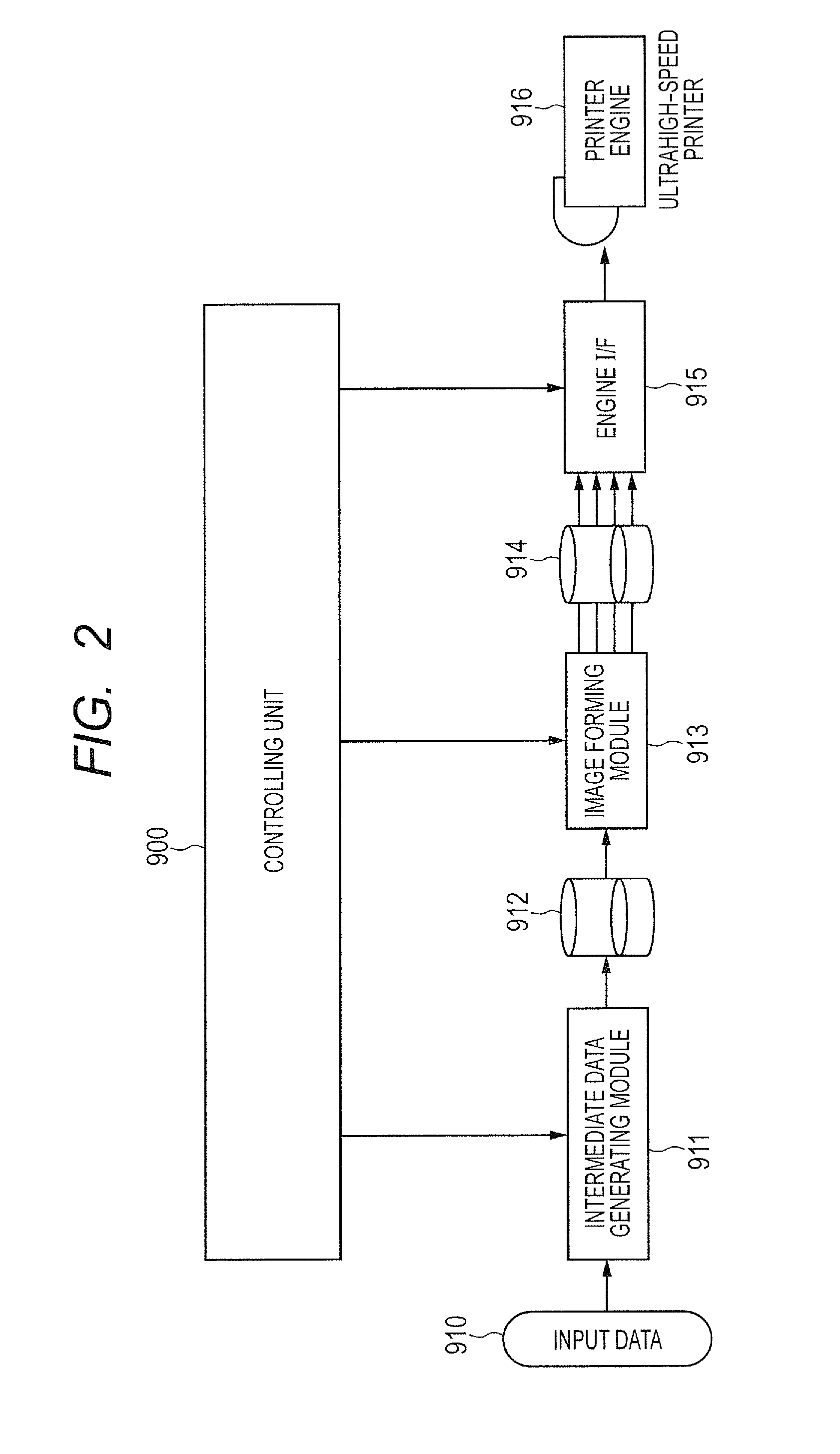
[0046]The image processing apparatus according to the first embodiment includes a controlling unit 100, an intermediate data generating module 111, an intermediate data spooler 112, an image forming module 113, a bitmap data buffer memory 114 and an engine I / F 115. Further, the controlling unit 100 includes a load level detecting unit 101 and an acceleration process controlling unit 102. The intermediate data generating module 111 is an example of a page processing unit, the load level detecting unit 101 is an example of a load deciding unit, and the acceleration process controlling unit 102 is an example of a controlling unit.

[0047]In the first embodiment, PDL data is input as input data 110 to the intermediate data generating module 111, and, in the input data, the data such as figure data o...

second embodiment

[0065]Subsequently, the second embodiment will be described. In the second embodiment, the constitution of the CPU chip is different from that in the first embodiment, and thus the core assigning process is different from that in the first embodiment. Other constitutions and configurations in the present embodiment are the same as those in the first embodiment. FIG. 13A is a block diagram illustrating the constitution of the CPU chip to be used in an image processing apparatus according to the second embodiment.

[0066]Here, a CPU chip 400 includes a first core 401, a second core 402, two L2 cache memories 411 and 412 respectively corresponding to the above cores, a last level cache memory 422, a memory 421, and an interprocessor interconnect 423 connected to the last level cache memory 422. Namely, the CPU chip 400 serves as the dual-core processor having two cores. In case of constituting the eight-core image processing apparatus by using the dual-core CPU chip like this, the four C...

third embodiment

[0077]Subsequently, the third embodiment will be described. In the third embodiment, the operation of the load level detecting unit 101 is different from that in the first embodiment. Namely, the constitution and the operation of the image processing apparatus other than the above operation are the same as those in the first embodiment. FIG. 16 is a flow chart indicating the operation of the load level detecting unit 101.

[0078]When the load level detecting process is started (S41), the property information of the page to be processed is accessed by the GetPage( ) function (S42). Thus, an inspection can be started to the page to be processed. Then, the inspection process is performed as an inspection process 1 in the cycle defined by a period f1 (S43). Simply, it is investigated and decided whether or not to be able to advance the process to S45 in the cycle (timing) of the period f1. Such decision is set to the flag, and branching decision is performed (S44). The processes in S43 an...


PUM


Abstract

Image processing apparatus and method capable of performing high-speed printing while suppressing an increase of memory size are provided. The image processing apparatus comprises: a page processing unit to perform processes of a plurality of pages in parallel; a load deciding unit to detect a load level in the page processing unit, for each page; and a controlling unit to control the page processing unit depending on a detection result by the load deciding unit, wherein the page processing unit assigns a thread of an edge extraction process to one or more image data in the page to be processed, and synthesizes an edge of each image data extracted by the thread, and the controlling unit comprises a thread priority order designating unit configured to designate priority order of the thread assigned by the page processing unit, depending on a result of the detection by the load deciding unit.

Description

BACKGROUND OF THE INVENTION[0001]1. Field of the Invention[0002]The present invention relates to image processing apparatus and method which are suitable for various kinds of printing such as character printing, photograph printing, figure printing and the like. Particularly, the present invention relates to the image processing apparatus and method which are related to a high-speed process for figure drawing.[0003]2. Description of the Related Art[0004]Conventionally, in order to draw a figure, a rendering method of extracting contour information (also called edge information) of the figure from the coordinate information or the like of the figure and forming an image based on the extracted contour information has been generally and widely used (e.g., Japanese Patent Application Laid-Open No. H04-170686). Here, the contour information is represented by a straight line, and a DDA (digital differential analyzer) algorithm has been known as a method of representing the straight line (...

Claims


Application Information

Patent Timeline
IPC IPC(8): G06F3/12G06K15/02
CPCG06F3/1245G06F3/1211G06F3/122G06F3/1284G06K15/02G06K15/1856G06K15/1857H04N1/40H04N1/00
Inventor NISHIKAWA, NAOYUKI
Owner CANON KK
Learn More