Eureka AIR delivers breakthrough ideas for toughest innovation challenges, trusted by R&D personnel around the world.

Power plug and power receptacle with over-temperature protection function

Active Publication Date: 2016-05-19
LI CHENGLI
View PDF2 Cites 6 Cited by
  • Summary
  • Abstract
  • Description
  • Claims
  • Application Information

AI Technical Summary

Benefits of technology

The present invention is a protection device that prevents overheating and fire hazards caused by poor electrical contact or over-current conditions.

Problems solved by technology

During long term use, the contact plates of the receptacle may lose their resilience so the contact between the contact plates of the receptacle and the plug may be affected, the receptacle or plug may be affected by humidity, or over-current conditions may occur during use.
In certain conditions, the copper alloy plates may generate a high temperature, which may melt the insulating housing of the receptacle and cause fire.
Similarly, in over-load conditions, the copper alloy plates of the receptacles can generate a high temperature, and the contact plates of the plug are also at high temperature, which may melt the insulating housing of the plug and cause fire and damage.

Method used


Image

  • Power plug and power receptacle with over-temperature protection function
  • Power plug and power receptacle with over-temperature protection function
  • Power plug and power receptacle with over-temperature protection function

Examples


Embodiment Construction

[0018]The preferred embodiments of the present invention are described in detail below with reference to the drawings. Although the preferred embodiments are shown in the drawings, it should be understood that the invention can be realized in various ways and is not limited to the embodiments described here. Instead, these embodiments are provided to make the disclosure more thorough and complete, and to convey the disclosure to those skilled in the art.

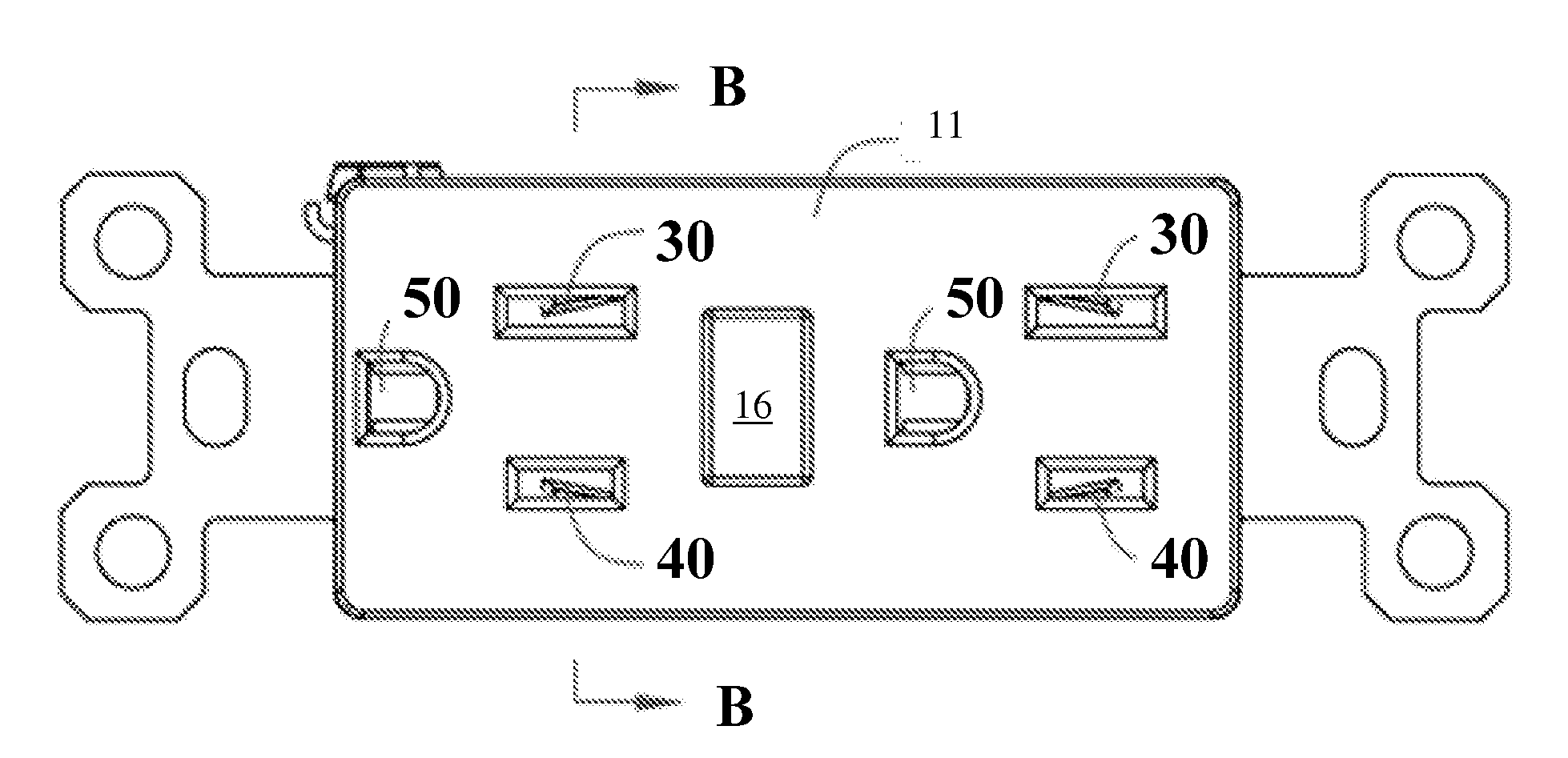
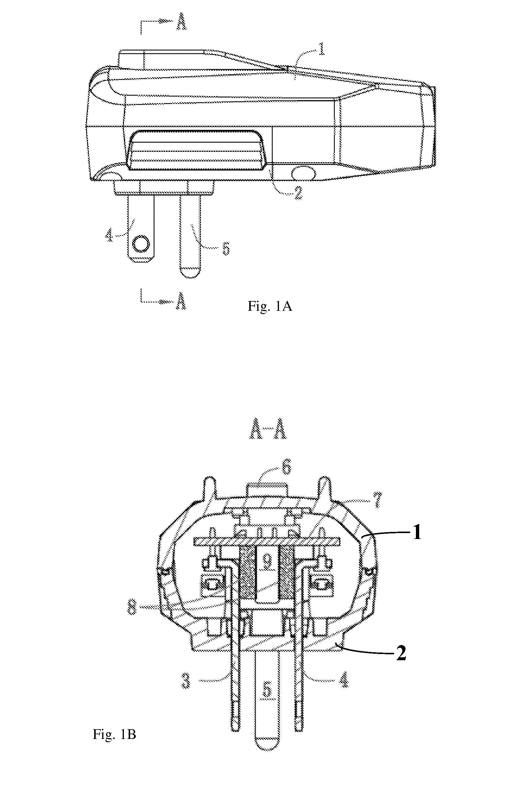
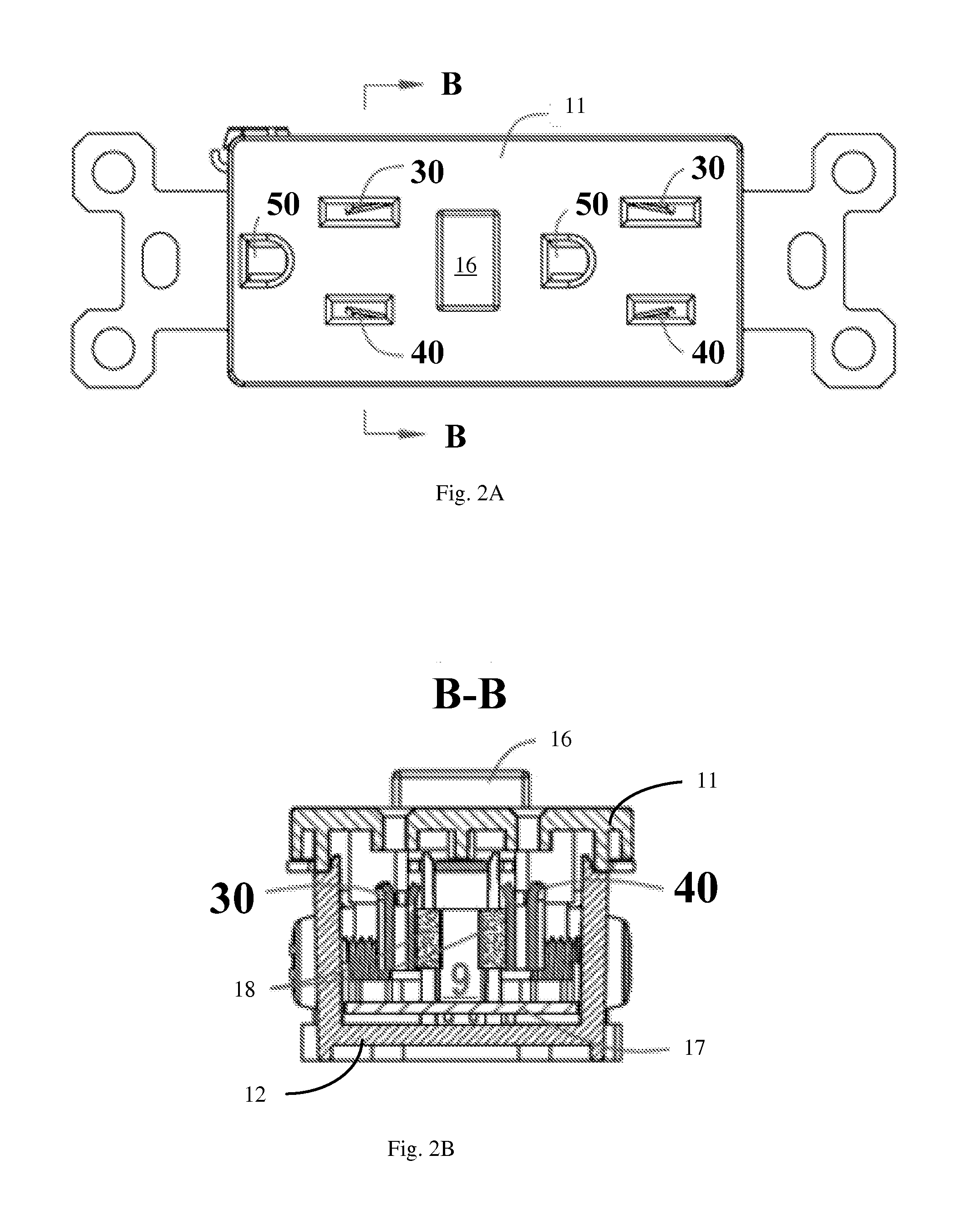
[0019]A power plug with over-temperature protection according to embodiments of the present invention is described with reference to FIGS. 1A-1B, 3A-3B and 5. The power plug has an insulating housing that includes an upper housing 1 and a lower housing 2. A control circuit board 7 is disposed inside the insulating housing and is electrically coupled to a trip mechanism. A reset button 6 protrudes out of the upper housing 1 and is connected to a reset switch 10 (FIG. 5) to form a reset switch assembly RESET. The input electrical condu...


PUM


Abstract

An electrical power plug or receptacle with an over-temperature protection function, including a reset switch operated by a solenoid that electrically connects and disconnects the input side and output side electrical lines, and an temperature-controlled switch disposed in thermal contact with one or more electrical conductor plates on the input or output side. The temperature-controlled switch is connected in series with the solenoid between the output side phase and neutral lines. When the temperature of the temperature-controlled switch is within a normal range, the switch is open and does not form a current path with the solenoid. When the temperature is at or above a threshold temperature, the temperature-controlled switch is closed, a current flows through the switch and the solenoid between the output side phase and neutral lines, and the solenoid operates the reset switch to disconnect the input side from the output side.

Description

BACKGROUND OF THE INVENTION[0001]1. Field of the Invention[0002]This invention relates to electrical power plugs and receptacles, and in particular, it relates to power plugs and receptacles that have a protection devices coupled to the conductor plates of the plug and receptacle.[0003]2. Description of the Related Art[0004]Electrical power plugs and receptacles are widely used in everyday life for connecting to electrical appliances. The electrical contact components such as plates or plates of plugs and receptacles are typically made of copper alloys, and their exterior housings use plastic materials for insulation. Typically, the receptacle is mounted in the wall, and the plug is connected to an appliance or another board having multiple receptacles. During long term use, the contact plates of the receptacle may lose their resilience so the contact between the contact plates of the receptacle and the plug may be affected, the receptacle or plug may be affected by humidity, or ove...

Claims


Application Information

Patent Timeline
IPC IPC(8): H01R13/713
CPCH01R13/7137H01R24/30H01R24/78H01R25/006H01R2103/00
Inventor LI, CHENGLI
Owner LI CHENGLI
Why Eureka
Eureka Blog
Learn More