One-part tooth implant, device for bending an implant, and method for bending an implant

a technology of abutment stud and a device, which is applied in the field of one-part tooth implant, can solve the problems of not being able to freely select the rotation position of the abutment stud not being able, or only being able, and achieving the effects of no damage to the bone bed, simple production, and reliable handling

Active Publication Date: 2016-05-26
HAGER & MEISINGER
View PDF14 Cites 11 Cited by
  • Summary
  • Abstract
  • Description
  • Claims
  • Application Information

AI Technical Summary

Benefits of technology

[0023]It is the object of the invention to provide a tooth implant, which is bendable in a simple and materially-careful manner, in particular also after implantation, i.e., already anchored in the jaw bone. It is a further object of the invention to provide a device for bending an object, in particular an implant, which enables the bending of the implant in a simple manner and in particular the bending after the implantation thereof such that a treatment which protects the implantation region is ensured, in particular that no damage of the bone bed is induced. In addition, the device is to be simply producible and simple and reliable in the handling. Furthermore, it is the object of the invention to provide a corresponding method for bending an object, in particular an implant, also after the implantation thereof.

Problems solved by technology

These formfitting connections, which are secured against twisting, do enable the simple transfer of the rotation position between a dental model and the situation in the mouth of the patient, but do not permit free selection of the rotation position of the abutment stud.
This is of particular significance in the case of the screw-shaped bony anchoring, since the rotation position of the implant results therein due to the implantation and is not freely selectable.
In the case of the screw-shaped tooth roots, which are advantageous for the anchoring, this is not possible because of the rotation position, which is predefined by the implantation position and which results by way of the screwing in up to a solid seat.
However, an adaptation of the orientation of the coronal part (abutment region) after implantation by bending, because of the high forces which act on the bone bed during the bending, is not possible or is only possible in cases having very good anchoring conditions, i.e., with long lengths of the artificial tooth root and with good bone conditions.
Known implants are often not adapted in the structure thereof to a bending process in the anchored state or are also not provided for this purpose.
In addition to the material titanium, the materials aluminum oxide ceramic and cobalt alloys have also been used for one-part tooth implants, wherein these materials from the group of ceramics and cobalt alloys have not proven themselves because of the lesser suitability for osseointegration.
However, bending after implantation is only possible in the case of this arrangement with very long anchoring geometries and very good bone quality.
The implementation of shorter anchoring geometries, as is necessary in the region of the mandible posterior teeth or in the case of low alveolar ridge height, is not possible, since a shorter implant causes excessively high reaction forces during the bending, which result in damage to the bony bed.
Damage to the bony bed is also to be expected upon use in softer bones.
Some instruments are very complex to produce and handle.
The soft tissue and bleeding of the operation wound make it more difficult to securely position the bending instrument at the point provided for it.

Method used


Image

  • One-part tooth implant, device for bending an implant, and method for bending an implant
  • One-part tooth implant, device for bending an implant, and method for bending an implant
  • One-part tooth implant, device for bending an implant, and method for bending an implant

Examples


Embodiment Construction

[0195]In the following description, the same reference numerals are used for identical and identically acting parts.

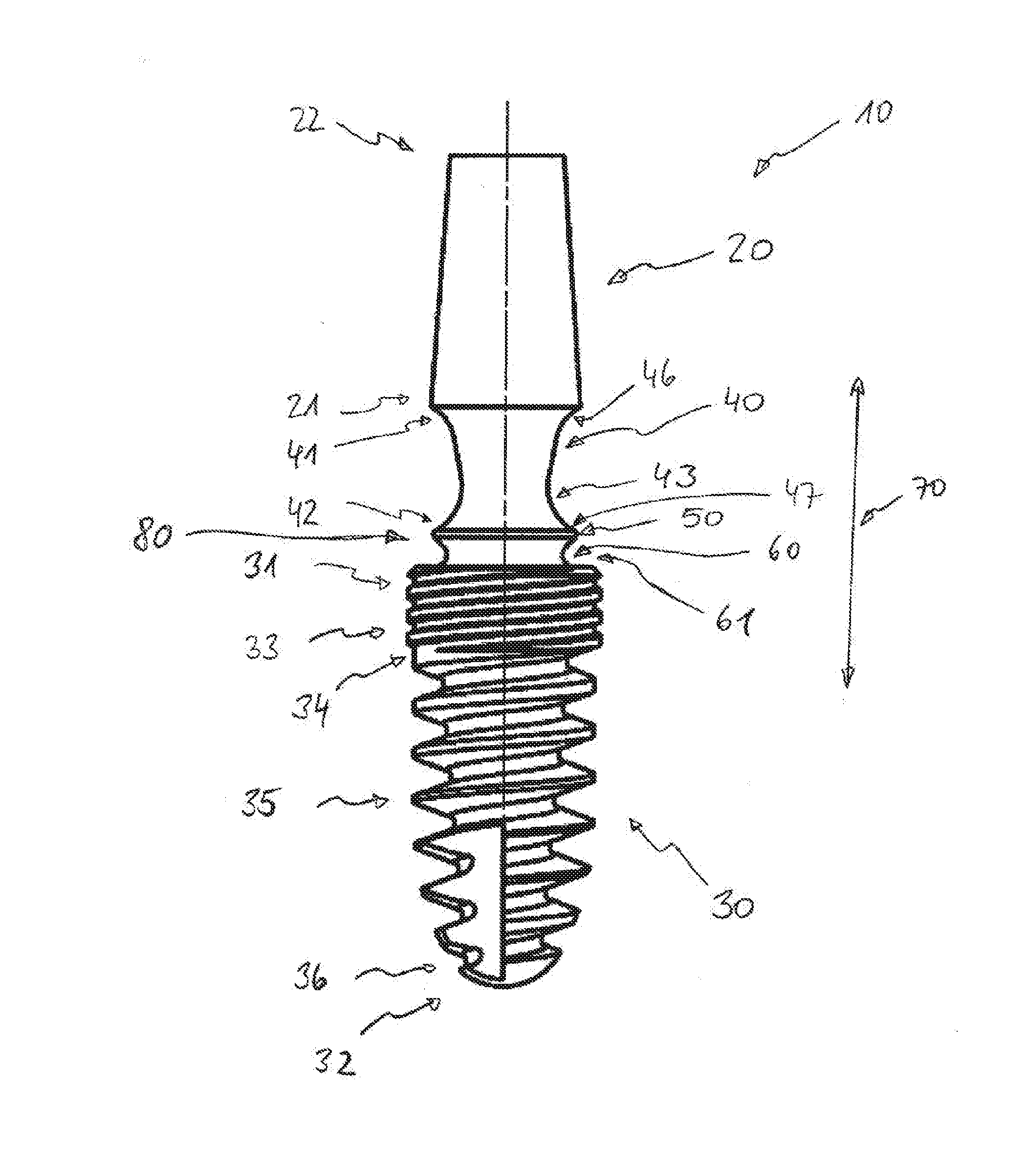
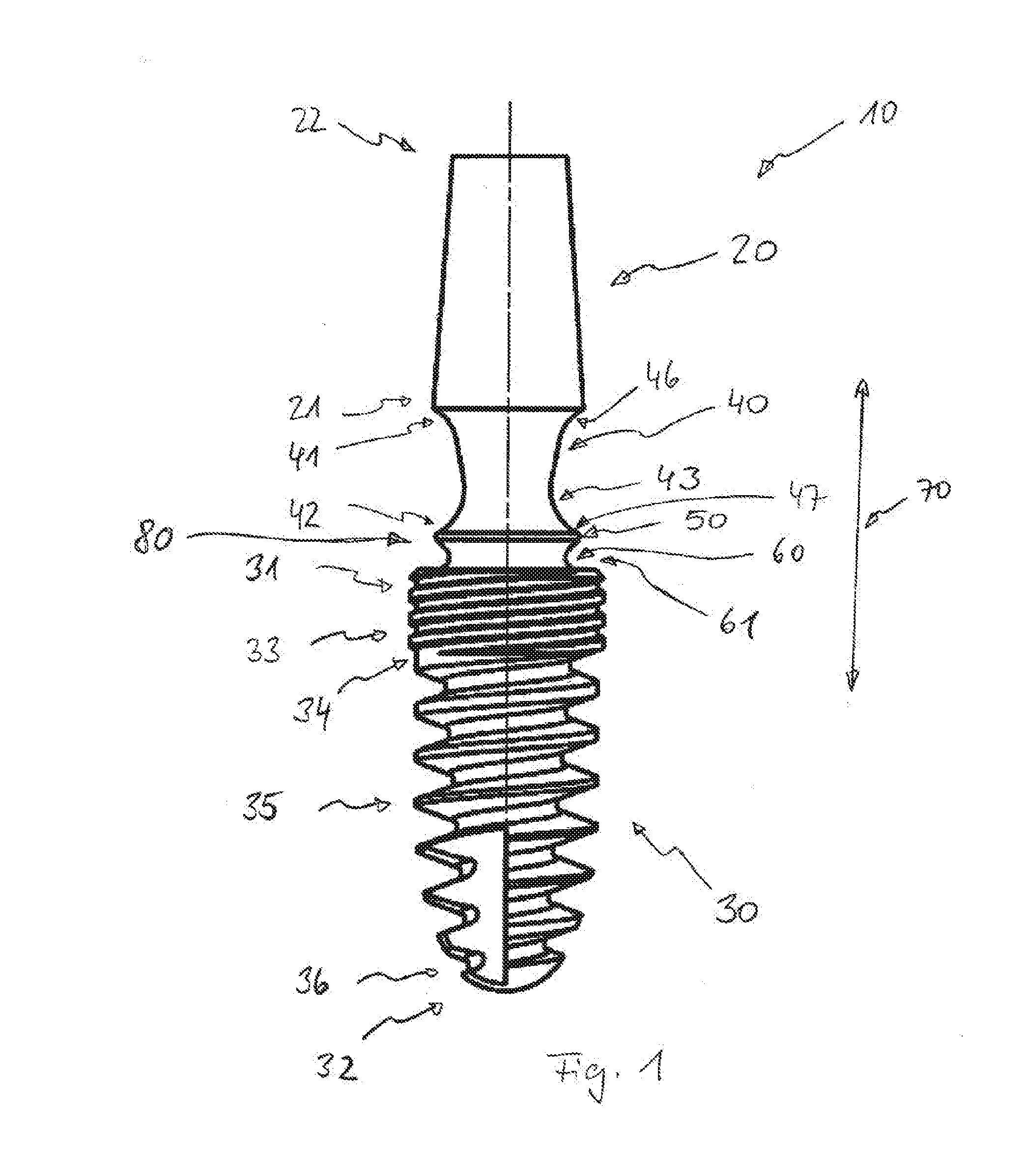
[0196]FIG. 1 shows an embodiment of an implant 10 according to the invention having an abutment region 20, also referred to as an abutment, which is designed such that a dental-prosthesis construction (not shown) is fastenable thereon. In addition, the geometry of an artificial tooth root or an anchoring region 30 is shown. An end 31 of the anchoring region 30 facing toward the abutment region will be located, for example, at or (slightly) below a bone level 80 after the implantation. Furthermore a bending region 40, also referred to as a bending zone, is provided, a collar-shaped element 50, and a bearing region 60.

[0197]The abutment region 20 has an end 21 facing toward the anchoring region and a free end or coronal end 22. The anchoring region 30 has the end 31 facing toward the abutment region and a free end or enossal end 32.

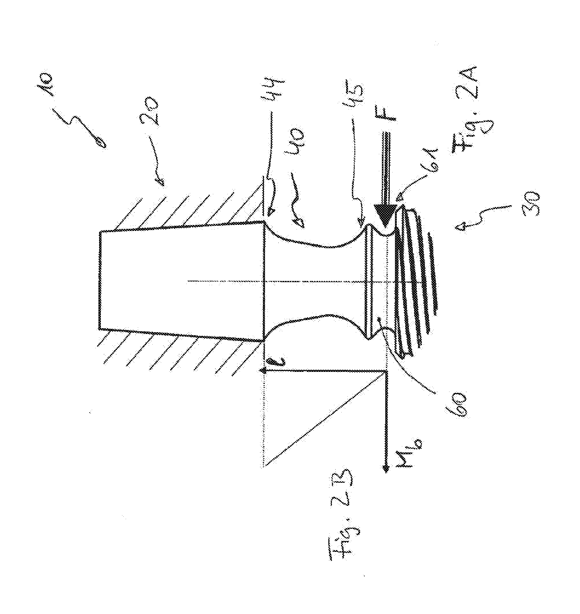
[0198]The bending region 40 is arranged...


PUM


Abstract

The invention relates to an implant (10) for anchoring in the human (optionally also in the animal) maxilla or mandible, a device (100) (an instrument) for bending an implant (10), a system, which comprises an implant (10) and a device (100) for bending an implant (10), and a method for bending an implant. As a result of the bending geometry, an implant (10) is provided which is bendable in a simple and materially-careful manner, in particular also after implantation, i.e., already anchored in the jaw bone. The device (100) for bending the implant (10) enables, as a result of the pliers-shaped design having corresponding holding (113) and support (123) units, the bending of the implant (10) in a simple manner, in particular the bending after implantation thereof, so that a treatment which protects the implantation region is ensured, in particular, no damage of the bone bed is induced. In addition, a method for bending the implant (10) is provided.

Description

CROSS-REFERENCE TO RELATED APPLICATION[0001]This application is a national stage entry of International Patent Application No. PCT / EP2013 / 001759, filed on Jun. 13, 2013, the entire contents of which are incorporated herein by reference.FIELD OF THE INVENTION[0002]The invention relates to an implant for anchoring in the human (optionally also in the animal) maxilla or mandible, a device (an instrument) for bending an implant, a system which comprises an implant and a device for bending an implant, and a method for bending an implant.BACKGROUND OF THE INVENTION[0003]Tooth implants are either known as one-part constructions or as two-part constructions. In the two-part embodiment, firstly an artificial tooth root is implanted into the jaw bone and it is subsequently connected to a second component, the abutment stud. The connection to the abutment stud is either performed intraoperatively or after a healing phase of several weeks. If the connection point between artificial tooth root a...

Claims


Application Information

Patent Timeline
Patent Type & Authority Applications(United States)
IPC IPC(8): A61C8/00
CPCA61C8/0075A61C8/0012A61C2008/0046A61C8/0089A61C8/0025A61C8/0053
Inventor MOSER, WALTER
Owner HAGER & MEISINGER
Why Eureka
Try Eureka